VARIO : Service & maintenance manual- rev. 4.2
Page 7.55
7.16.
DISASSEMBLING THE BELTS AND MAGNET
7.16.1.
S
HORT BELT DISASSEMBLING
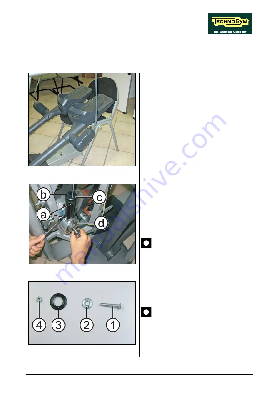
Figure 7.16-1
Carry out the procedure described in paragraph:
7.7.1. “Disassembling the centre guard”, 7.7.3.
7.7.4. “Swivel belt connector guard”.
1.
Use a chair or bench to raise the pedal levers,
so as to eliminate the tension from the belts,
as shown in the figure.
Figure 7.16-2
2.
Cut the 2 cable ties
(a)
and remove the 2
half-guards
(b)
and
(c)
that prevent twisting
of the belt.
3.
Unscrew the swivel connector
(d)
using a
6mm hexagonal wrench, and holding the nut
on the opposite side in place with a 17mm
wrench, as shown in the figure.
CAUTION: During reassembly, take
care to re-insert the swivel connector
on the correct side: with the snap ring
toward the outside and the deeper
end, with its spacer, on the inside.
Figure 7.16-3
CAUTION: During reassembly, follow
the sequence indicated in the figure at
left.
Continued on following page...
Summary of Contents for Vario Excite + 500
Page 1: ...V VA AR RI IO O E X C I T E REV 4 2...
Page 2: ......
Page 4: ......
Page 10: ...VARIO Excite Service maintenance manual rev 4 2 Page vi Page intentionally left blank...
Page 58: ...VARIO Excite Service maintenance manual rev 4 2 Page 5 6 Page intentionally left blank...
Page 170: ...VARIO Excite Service maintenance manual rev 4 2 Page 7 70 Page intentionally left blank...
Page 206: ...VARIO Excite Service maintenance manual rev 4 2 Page 9 26 Page intentionally left blank...
Page 208: ...VARIO Excite Service maintenance manual rev 4 2 Page 10 2 Page intentionally left blank...
Page 219: ......


