background image

Call: 1-631-648-7481 or Visit:: www.technocnc.com/technical-support/

1

HD II Tabletop Manual

NK105G2

Techno CNC Systems, LLC ©2018

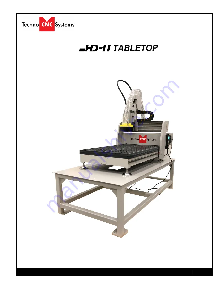
This document will provide a quick guide to the set up and operation of the Techno HD II Tabletop 
CNC Router equipped with the NCstudio controller. 

Tabletop CNC 

Router Manual

Summary of Contents for HD II Tabletop

Page 1: ...chnical support 1 HD II Tabletop Manual NK105G2 Techno CNC Systems LLC 2018 This document will provide a quick guide to the set up and operation of the Techno HD II Tabletop CNC Router equipped with t...

Page 2: ...tepping the machine Page 12 3 3 Modifying the Jog Speed and Step Size 3 4 Feedrate Override Page 13 3 5 Adjusting the XYZ Position WCS User Origin Page 14 3 6 Loading a G code file Page 15 3 7 Running...

Page 3: ...Keep cutting tools clean and sharp Lubricate and change accessories when necessary Cables and cords should be inspected regularly Keep controls clean and dry 17 Before using check for damaged parts An...

Page 4: ...Call 1 631 648 7481 or Visit www technocnc com technical support 4 HD II Tabletop Manual NK105G2 WARNING THE SPINDLE WILL BE DAMAGED IF UNBALANCED EQUIPMENT IS USED AIR SUPPLY MUST BE FILTERED AND DRY...

Page 5: ...p Quick Set up 1 2 Have a licensed electrician connect power to the controller The machine requires 220V single phase 15amp power in order to operate Plug the power cable into the rear of the machine...

Page 6: ...by giving it a turn clockwise Then activate the machine by pressing the green POWER but ton Power is now applied to the machine The green light will illuminate Emergency Stop Power Enable Power Disabl...

Page 7: ...ns that rely on a reference position will be invalid Once the machine has moved to its homing position on each axis it will stop and enter an IDLE state and will be ready to use Pressing OK will initi...

Page 8: ...Z step increment Z Movement Input the number 9 X Movement Input the number 6 Z Movement Input the number 3 Menu Screen Input a decimal point Shift Key Switch between Jog and Step modes Down Directiona...

Page 9: ...egative direction left of table input the number 4 Manually turn spindle on off input the number 5 Move X axis in the positive direction right of table input the number 4 Decrease feedrate override in...

Page 10: ...I Tabletop Manual NK105G2 Start machining Pause machining Up direction arrow when navigating menus Stop machining Cancel Escape Switch between jog and stepping modes Auxilliary key Down direction arro...

Page 11: ...ift key and then select a second key Increase spindle RPM Switch between work relative and machine absolute cooridinates When it reads X1 Y1 Z1 that is relative When it reads X Y Z that means absolute...

Page 12: ...e Jog and Step To switch between these modes press the Shift button The mode will be displayed on the bottom left of the screen Jog Also known as continuous mode When a directional arrow is pressed th...

Page 13: ...ress ESC When inputting a decimal increment you must enter the value as 0 Zero decimal your increment Low Speed High Speed Step Sizes To move the cursor use the Up and Down directional arrows Enter a...

Page 14: ...from The machine should be jogged to the corner of the material by using the directional arrows on the keypad Once the machine is in location press to set XY zero The coordinates on the controller wi...

Page 15: ...is ready to run the G code file To run the G code file simply press the start button Once the spindle has reached its programmed speed the machine will move into position to start the first cut The f...

Page 16: ...e file will be obeyed Yes means speed will be overrode by the controller 4 2 Setting the Override Speed for a G code file From the main screen press Menu to access the Menu screen Use the up and down...

Page 17: ...m 2 there needs to be another number next to X Y and Z and in this case that would be number 2 In order to change between each coordinate system go to the Main Menu 3 Operations and finally 6 Select W...

Page 18: ...o to the 3 Operations then go to 3 Select Line No and then type in the corresponding line numbers you would like to start and stop at From the main screen press Menu to access the Menu screen Use the...

Page 19: ...Exit the menu and restart the machine The new settings will now be applied 6 Now jog to your starting point and set your X and Y origin This position should be above the rotary part Note The X axis w...

Page 20: ...File active file name Note These numbers can vary All following settings can be found by pressing the Menu key and are worded abbreviated as you would see them on screen Note All settings with on scre...

Page 21: ...File Rows 2 Columns 2 Row Space 1 969 Col Space 1 969 Delay 50 LOAD NOW 8 Origin Last 1 X 0 Y 0 Z 0 2 ____ _____ 3 ____ _____ repeats through 8 9 Nearby Process 4 Oper Param 1 G00 Speed 200 00 in min...

Page 22: ...YES 3 S off at End YES 11 Ratio on Manu YES 12 DXF Params 1 Lifting Height 0 039 2 Process Depth 0 039 3 1 st Point as 0 YES 4 Shape Process NO 5 Bottom Process NO 6 Metric Size NO 13 ENG Params 1 Lif...

Page 23: ...ight 512 18 ENG Unit YES 5 MFR Param PASSWORD 33587550 1 Velocity 1 Decel Dist 0 394 inch 2 Approach Speed 20 00 in min 3 Run Acc 20 00 in sec 2 4 Dry Run Acc 20 00 in sec 2 5 Max Turn Acc 30 00 in se...

Page 24: ...0 Z 8 465 5 Change Stroke 1 Strk Upper Lmt X 15 748 Y 15 748 Z 0 2 Strk Lower Lmt X 0 Y 0 Z 3 937 6 Ref Point Set 1 RefP Speed X 70 in min Y 70 in min Z 60 in min 2 RefPDir X Negative Y Negative Z Pos...

Page 25: ...NO 3 Axis Backlash X 0 0 Y 0 0 Z 0 0 10 Calib Thickness 0 669 inch will vary slightly 11 Algorithm YES 12 Arc Incriment YES 13 Arc Tolerance 0 079 14 Forward Look Seg 50 15 Sign of BK REF YES 16 Safe...

Page 26: ...ystem Upkeep 1 Language 1 Chinese 2 English 2 Export Log 3 System Update 4 Register 5 Help Spec Help Message Show Delay Value 1 Unit s 6 Reboot 7 Exit 8 Delete Log 9 Disk Space 10 Delete Info 11 Modif...

Page 27: ...The grease fitting for the X axis ballnut is located on the rear face of the gantry head Lubricating the ZAxis The grease fitting for the Z axis ballnut is located on the top of the spindle plate NOT...

Page 28: ...re peak mechanical performance Thoroughly clean components of any excess lubrication before fresh coating Ball screw assemblies should be lubricated via the grease nipple using a grease gun Check your...

Page 29: ...off on off on off on on LEADSHINE DMA860H MICRO STEP DRIVERS 3 times WEIHONG NK105 G2 SCHENIDER ZB2 BE102C N C SCHNIEDER LC1D25BDC EMI X AMP Y AMP Z AMP TIGER TECH JBK5 500VA 220 V IN 50 V OUT MEAN WE...

Page 30: ...nd Parts that Techno deems validly subject to a warranty claim will be repaired or replaced in Techno s sole discretion without charge Repaired items may include new or refurbished replacement parts R...

Page 31: ...by personnel unauthorized by Techno Modifications to and tampering with the Product or Part Use of non standard parts or accessories without prior written approval from Techno Use of Product or part...

Page 32: ...ck Warranty claims will not be reviewed or remedied unless the warranty registration is received by Techno within thirty 30 days of the purchase date All warranty issues must be handled through Techno...

Reviews: