


75
Sensor correction
This setting is only displayed if "Measured variable" is set to "User".
The value of the DL input can be corrected by applying a fixed differential value.
Sensor error
This setting is only displayed if sensor check is active and "Measured variable" is set to "User".
When "Sensor check" is active, the sensor error of a DL input is available as an input variable for func
-
tions: status "No" for a sensor that is working correctly and "Yes" for a defect (short circuit or lead
break). This allows the controller to react to the failure of a sensor, for example.
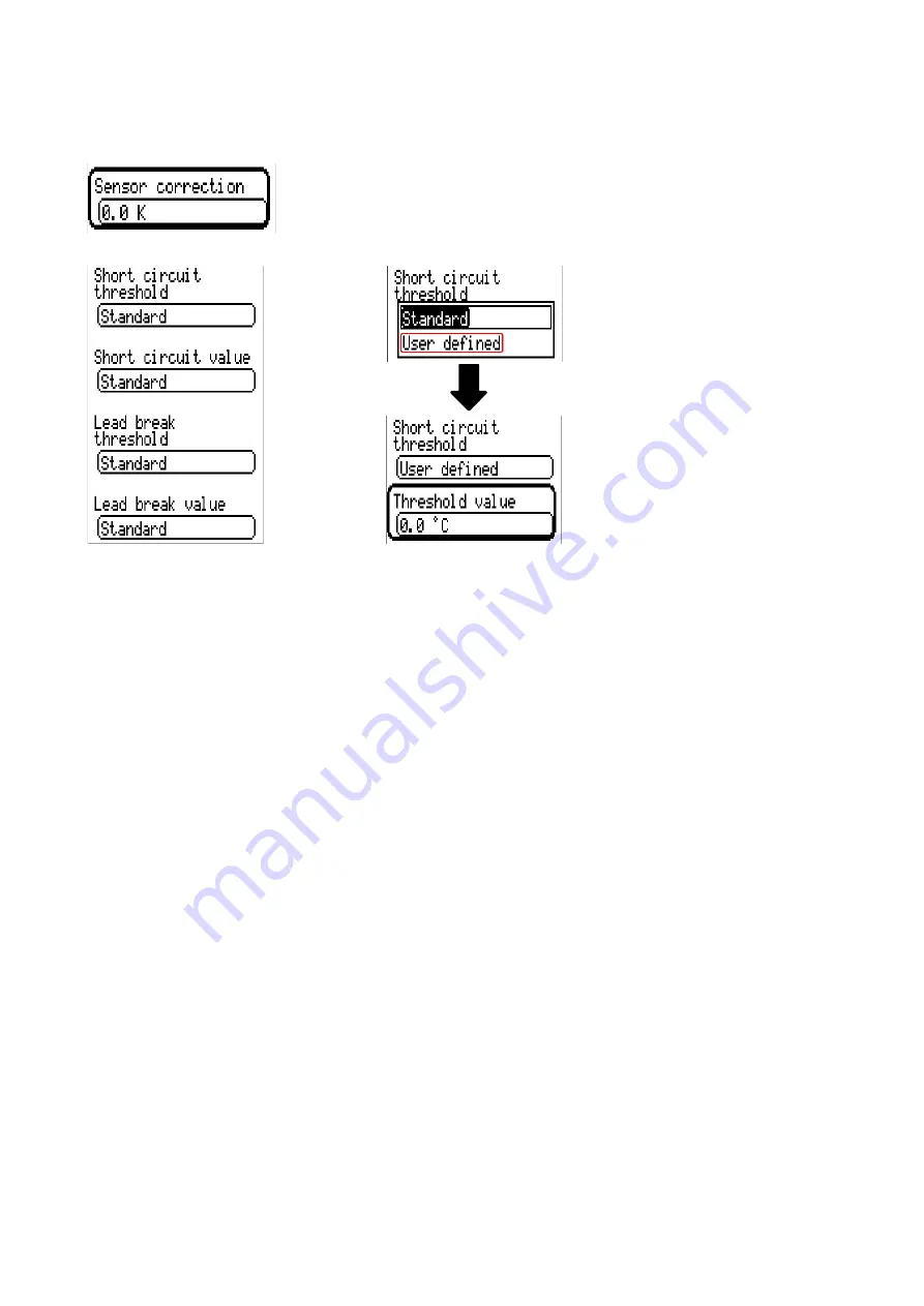
If the Standard thresholds are selected, a short circuit will be indicated if the value falls below the
measurement limit and a lead break will be indicated if the value exceeds the measurement limit.
The Standard values for temperature sensors are -9999.9 °C for a short circuit and 9999.9 °C for a
lead break. Those values are utilised in the internal calculations in the event of an error.
By selecting the thresholds and values for short circuit and lead break appropriately, a fixed value can
be specified for the controller in the event of sensor failure at the transmission node, in order to allow
a function to continue operating in emergency mode (fixed hysteresis: 1.0 °C).
The short circuit threshold must be defined below the lead break threshold.
In System values / General, a sensor error for all inputs, CAN inputs and DL inputs is available.
DL digital inputs
The DL bus is configured for the transfer of digital values as well as analogue. However, there is not
yet any use for this at present.
The parameters are programmed in almost exactly the same way as for the DL analogue inputs.
Under Measured variable / User the Display for the DL digital input can be changed to No / Yes.
Bus load of DL sensors
A 2-pole cable provides both the power supply and the signal transfer for DL sensors. An additional
power supply by means of an external power supply unit (such as with the CAN bus) is not possible.
As the DL sensors have a relatively high power demand, the "bus load" must be considered:
The CAN-EZ3 energy meter provides a maximum bus load of
100 %
. The bus loads of the DL sensors
are listed in the technical data of the relevant DL sensors.
Example: The DL sensor FTS4-50DL has a bus load of 25%. Consequently up to four FTS4-50DL sen
-
sors can be connected to the DL bus.
Summary of Contents for CAN-EZ2
Page 5: ......
Page 62: ...62 Messages This menu item displays activated messages Example A message is active...
Page 98: ......
Page 99: ......


