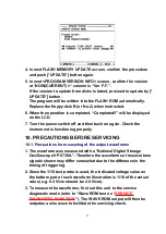
4. In next FLASH MEMORY UPDATE screen, confirm the procedure
and push [*UPDATE*] button again.
5. In next <PROGRAM VERSION INFO> screen, confirm the version
at “NOW(CURRENT) =“ column is “Ver F.F.”.
If the version to update from disks is latest, proceed to update by [*
UPDATE*] button.
The program will be written into the FLASH ROM automatically.
Replace the floppy disk B (or No.2) when instructed.
6. When the operation is completed, “Completed!!” will be displayed
on the LCD.
7. Turn the power switch off and then back on again. Check the
instrument is functioning properly.
10. PRECAUTIONS BEFORE SERVICING
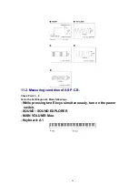
10.1. Precautions for measuring of the output waveforms
1. The waveform was measured with a “National Digital Storage
Oscilloscope VP-5730A”. Therefore the waveforms of musical tone
signals shown may differ somewhat due to the difference in the
timing of triggering.
2. Since the 1/10 test probe is used, the indicated voltage value on
the bottom part of each waveform illustration is 1/10 of the actual
value (e.g. 0.2 V/cm should be 2.0 V/cm).
3. To measure the waveforms, first set this unit to the service
diagnostic mode (refer to “Wave ROM test on “
SERVICE
DIAGNOSTIC FUNCTION
”). The WAVE ROM output will then be
outputas a sine wave to facilitate the servicing check.
23
Summary of Contents for SX-PR603/M
Page 33: ...C15 ECCR1H100D5 10PF 1 AS 33...
Page 38: ...D12 MA165 DIODE 1 MKB1 38...
Page 47: ...L8 QLQGT1D600MA COIL 1 AS 47...
Page 50: ...50...
Page 59: ...59...
Page 60: ...60...
Page 61: ...18 PACKAGING 61...

