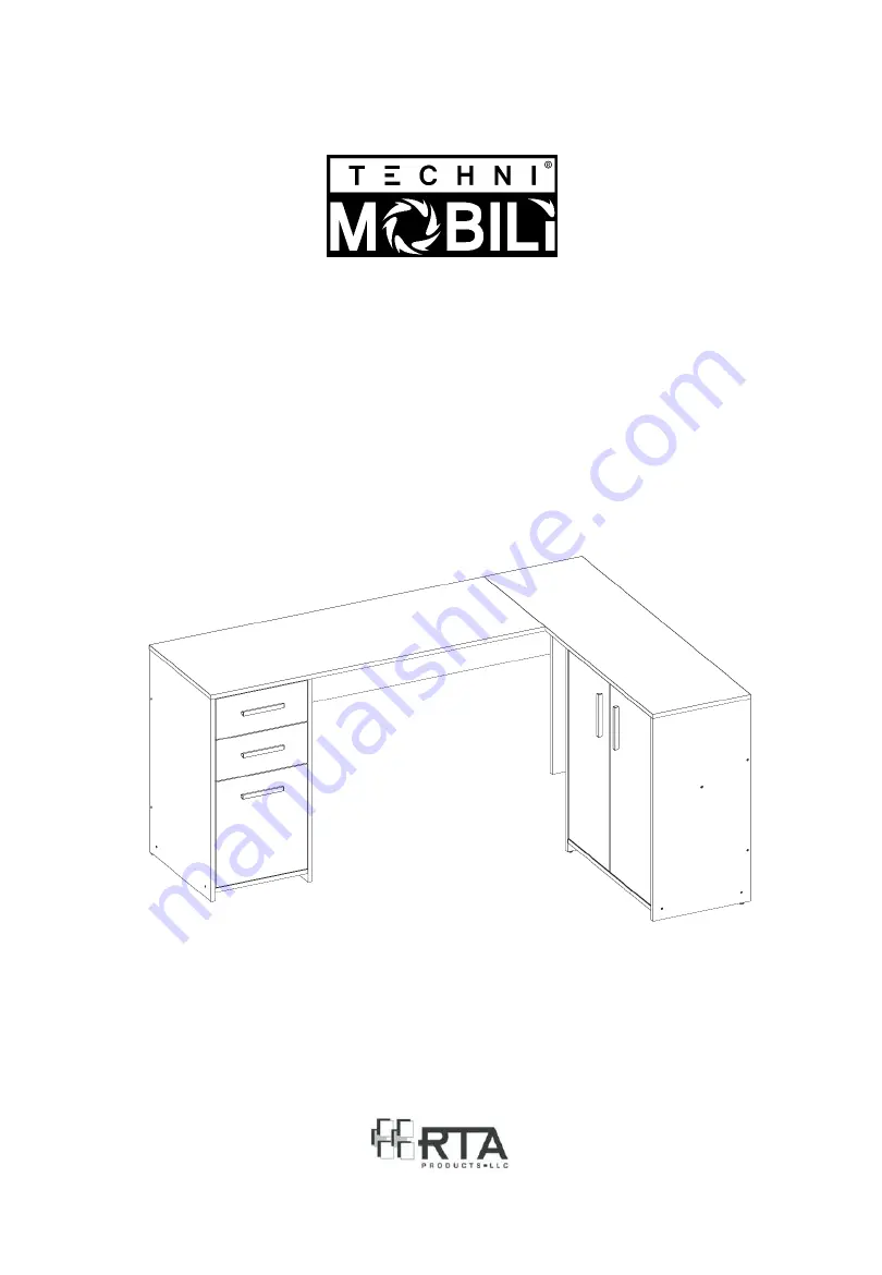
Thank you for purchasing our product.
MODEL RTA-914LD
ASSEMBLY INSTRUCTIONS
REV.022021-0
Page 1: ...Thank you for purchasing our product MODEL RTA 914LD ASSEMBLY INSTRUCTIONS REV 022021 0 ...
Page 2: ...ead carefully the assembly instructions before the installation Do not discard this manual or any of the packaging material until the unit has been completely assembled Might require two people P 1 RTA 914LD P 1 ...
Page 3: ... for right cabinet Bottom panel for right cabinet 9 x1 10 x2 Middle shelf for right cabinet Back panel for right cabinet 11 x1 12 x2 Left panel for right cabinet Back Right horizontal panel 13 x2 14 x1 Short Right tabletop Corner vertical support panel 15 x2 16 x1 Door for right cabinet Door for left cabinet 17 x2 18 x2 Drawer front panel Drawer right panel 19 x2 20 x2 Drawer left panel Drawer bot...
Page 4: ... H 16 ST3x12 I 22 15mm plastic adhesive covers J 16 M4x23 nails PART QTY ITEM K 9 12x12x6mm Nail in glide stud L 5 128mm Handle M 5 15x15x40mm Angle bracket N 2 Sets Sliders Set of 4 pcs O 6 26mm hinges with 5mm shim P 2 60x60mm Metal plate Q 1 16x8x8mm Plastic door stopper R 1 Touch up NOTE You will need for the assembly a Phillips screwdriver and mallet hammer not included 1 2 3 4 5 6 7 8 9 10 1...
Page 5: ...bly step it is a guide for when you are actually doing the assembly using this kind of hardware Cam Bolt Cam Lock 1 Screw the bolt into the corresponding panel 2 Place the other panel over the panel with the bolt then insert the cam lock to join the bolt s head If the cam lock does not want to enter check its proper alignment There might be a very small gap between the panels which is normal 3 Tur...
Page 6: ...t overtighten or force the screws as they might break strip damage the threads of the holes or get stuck inside the part Make sure you understand which hardware will be used on each step Using the wrong size of screw bolt or pin might strip the threads or cause damage to the part in which it is being used To avoid misalignments always leave the screws loose and tighten them until all pieces are po...
Page 7: ...4LD P 6 Separate all the sliders pieces N according to their shape no assembly is done here The Flat ones will be used in the next step The L shaped go on the drawer and will be used until step 25 1 STEP 2 Hardware N Sliders 2 Sets 1 9 8 2 3 4 11 7 18 18 19 19 L shaped Use until step 25 on the drawer RIGHT LEFT FLAT Use on step 3 inside the unit RIGHT LEFT ...
Page 8: ...ards the front and facing down For best results attach at the front of the panels first STEP 3 Hardware Tools H ST3x12 8 Pcs N FLAT 4 pcs NOT INCLUDED Wheel goes at front and facing down Hole at the front Front Front 4 Front 4 2 Front 2 best results attach at the front of the panels first Attach the sliders on these holes ...
Page 9: ...ble panel 2 to panel 1 with screws D as shown Assemble panel 3 to panel 2 with screws D 2 1 STEP 4 Hardware Tools D ST3 5x40 Flanged 2 Pcs NOT INCLUDED 1 2 Top STEP 5 Hardware Tools D ST3 5x40 Flanged 2 Pcs NOT INCLUDED 3 2 1 ...
Page 10: ...ly attach the glides K to the bottom of the panels 2 and 4 STEP 6 Hardware Tools D ST3 5x40 Flanged 4 Pcs E ST3 5x40 Flat 1 Pcs K Glide studs 4 Pcs NOT INCLUDED Top 2 1 3 4 Top D E Screw E is only for the top hole on panel 4 D D K Assemble panels 8 and 9 to panel 7 with screws D STEP 7 Hardware Tools D ST3 5x40 Flanged 3 Pcs NOT INCLUDED Top 8 9 7 ...
Page 11: ...op Finally attach the glides K to the bottom of panels 7 and 11 This illustration shows the same parts from step 9 but view from the left 8 STEP 8 Hardware Tools D ST3 5x40 Flanged 3 Pcs NOT INCLUDED 9 11 STEP 9 Hardware Tools D ST3 5x40 Flanged 5 Pcs E ST3 5x40 Flat 1 Pcs K Glide studs 4 Pcs NOT INCLUDED 8 7 10 10 11 This illustration shows the same parts from step 10 but flipped over IMPORTANT O...
Page 12: ... NOT INCLUDED 4 5 11 In panel 5 attach to the holes closer to the edge Attach the glide K to the bottom of panel 14 then assemble the panel to panel 5 with screws F as shown STEP 11 Hardware F ST3 5x25 3 Pcs K Glide stud 1 Pc NOT INCLUDED 5 14 Panel 14 attaches to panel 5 at 16mm 3 4 from the edge K ...
Page 13: ...s 2 Pcs I Covers 2 Pcs NOT INCLUDED Cam lock alignment C I 5 4 Cam lock alignment alignment C I I 5 With the help of another person join panel 12 to panels 5 and 11 Then insert the cam locks C in panel 12 making sure they are aligned and turn the cam locks as shown and as explained in page 4 Finally cover the cam locks with I STEP 13 Hardware C Cam locks 4 Pcs I Covers 4 Pcs NOT INCLUDED the cam l...
Page 14: ...t the door stopper Q into the corresponding hole on panel 4 Attach to panels 15 and 16 the handles L with screws F and the hinges O with screws G as shown STEP 14 Hardware G ST4x12 10 Pcs M 5 Pcs Q Door stopper 1 Pc NOT INCLUDED STEP 15 Hardware F ST3 5x25 6 Pcs G ST4x12 12 Pcs L 3 Pcs O 6 pcs NOT INCLUDED 5 12 10 16 15 15 F G For the handles For the hinges F G 3 M M Q ...
Page 15: ... close smoothly adjust their alignment by loosening up the indicated screws adjusting the door position then re tightening the screws STEP 17 NOT INCLUDED large doors to panels respectively with screws STEP 16 Hardware G ST4x12 12 Pcs NOT INCLUDED 2 15 7 11 15 15 16 Loosen these 2 screws to adjust the height Loosen this screw to adjust side to side Loosen this screw to adjust the depth ...
Page 16: ...efully place the tabletops 6 and 13 over the frame built in step 16 then insert the cam locks C in the corresponding holes on panels 2 4 7 and 11 and turn them to lock the pieces as explained in page 4 Finally cover the cam locks with I STEP 18 Hardware B Bolts 8 Pcs NOT INCLUDED STEP 19 Hardware C Cam lock 8 Pcs I Covers 8 Pcs NOT INCLUDED 6 13 2 7 11 4 6 13 Cam lock alignment alignment C I ...
Page 17: ...he metal plates P in between the panels as shown For each of the 2 small drawers assemble the drawer side panels 18 and 19 to the drawer back panel 21 with screws E as shown STEP 20 Hardware G ST4x12 18 Pcs P 2 Pcs NOT INCLUDED 6 13 View from underneath STEP 21 Hardware Tools E ST3 5x40 Flat 4 Pcs NOT INCLUDED 21 19 18 M P M ...
Page 18: ...ith Cam lock alignment C I B 17 19 18 17 For each drawer assemble the handle L to the drawer front panel 17 with screws F from inside The groove on panel 17 go on the bottom of the drawer The illustration shows the drawer upside down STEP 23 Hardware Tools F ST3 5x25 4 Pcs L Handle 2 Pcs NOT INCLUDED STEP 24 Hardware Tools J Nails 16 Pcs NOT INCLUDED For each drawer place the panel 20 on the botto...
Page 19: ...to the orientation of the sliders as indicated ATTENTION Incorrect Will raise 1 and drawer won t fit Correct The wheels go towards the back of the drawer Insert the drawers into the unit starting with the bottom one You might need to insert them an angle with the front facing down If the drawers don t fit please review the assembly of the steps 3 and 25 STEP 26 Attach the sliders through the indic...
Page 20: ...ALL DONE Give yourself a nice pat on the back You did a great job P 19 RTA 914LD P 19 ...
Page 21: ... lifted by at least 2 persons when moving in the same or adjacent rooms Before moving the unit make sure to secure or remove any object that is heavy or might fall off Please note that lifting from the tabletop with too much weight inside the unit might lead to part damage separation When lifting the unit use both hands and bend your knees not your backs When transporting the unit to places far aw...
Page 22: ...anty or merchantability or of fitness for a particular purpose Please note all desks made with PVC Laminate surface should not be exposed to direct sunlight as it may damage the material Damage of this nature is not covered under this warranty RTA Products will not be responsible for indirect special incidental or consequential damages This warranty is limited to merchandise purchased in the Conti...
Page 23: ... REPLACEMENT PARTS ORDERS _________________________________________________________________ VISIT WWW TECHNIMOBILI COM CLICK ON SUPPORT TAB Scan QR Code to order replacement parts OR EMAIL US SUPPORT RTAPRODUCTS COM P 22 RTA 914LD P 22 ...