16
3.4 Instruction of Input & Output
The following input interfaces and output interfaces are corresponding to the signal pins which are defined as
“Min, Mout, Ein, Eout” at the above socket. It also corresponds to the interface at the “IO Test” display window.
After setting, the function of IO interface can be tested at the “IO Test” display window.
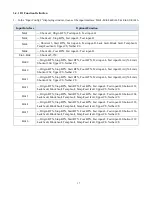
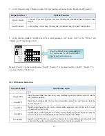
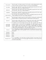
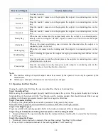
The interfaces, in the following table, can be set at the “Input Config” or “Output Config” of “System Config
2” of teaching pendant. It can define the special function for the following input & output interfaces which are
corresponding to the above sockets.
Connection of DB37 plug


