background image

P7x2

P13

2 9

2 1

2 2

C2 5

R ed

B lack

R ed

C2 4

B lack

Summary of Contents for King Lizard

Page 1: ...From the Makers of TTR 892 10 ASSEMBLY INSTRUCTION MANUAL ...

Page 2: ... H ead Module T esting B ody Module T esting S tickers P 2 T ools Y ou May N eed P 2 P 2 Plastic Parts P 4 P 5 P 8 P 19 B ody Module Assembly P 17 P 34 H ow to Play P 35 Escape Mode F ollow me Mode P 36 P 37 W arning P 38 T rouble S hooting P 39 C o n t e n t s ...

Page 3: ...d if you don t run away the lizard will The King Lizard functions with two modes Follow me and Escape With the 2 mode switch when the infrared IR sensor is activated in the Elude mode the King Lizard will act startled The frill will deploy jaws gape and LED eyes blaze all before scurrying away to a safe distance When the IR sensor is activated in the Follow me mode your King Lizard will bluff the ...

Page 4: ...TY QTY P13 P11 P12 Motor With Connector Motor With Connector Battery Holder With Connector 1 1 QTY QTY P15 P14 Black W Short Wires Black Red Red PC Board With Connector 1 1 QTY QTY P17 P16 Frill Spare Parts 1 1 QTY QTY P18 1 QTY P20 Adhesive Tape P19 W Long Wires 3 DC 6V ...

Page 5: ... 2 2 1 E 5 4 3 2 6 7 8 9 1 B 10 11 12 9 12 16 17 18 19 20 21 22 23 24 25 15 14 10 11 13 8 3 4 5 2 1 C L 6 7 C3 C4 R 1 6 7 8 9 A8 A11 A 1 A2 2 3 5 12 13 11 10 10 9 4 A 1 2 3 4 D 012 Plastic Parts burr burr burr Tip cut off the burrs before assembly Spare Parts Spare Part 4 ...

Page 6: ...H e a d M o d u l e A s s e m b l y 5 1 C9 2 C6 C15 C5 ...

Page 7: ...S ide V iew P2 R ed P8 S hort C13 P1 P14 B 3 R ed B lack 6 3 4 5 1 1 1 2 2 1 1 W Short Wires ...

Page 8: ...Make sure is positioned as shown below It is to assist you in assembling C8 correctly 7 6 7 8 1 2 2 C8 B4x6 Black Red ...

Page 9: ......

Page 10: ...9 9 10 P19 A13 P18 A7 A9 A9 A10 A10 Cut the frill as illustrated below Make sure adhesive tapes come with thin glued films while tearing off Extra frill included ...

Page 11: ...A10 A10 A13 A7 T he opposite no color side should be facing up N o stickers on the colored side 10 11 F r o n t B a c k A9 ...

Page 12: ...P u l l 11 12 A9 A9 A10 A10 A13 A7 ...

Page 13: ...12 A9 A13 A10 A10 Note Frill is not pictured below to clearly illustrate assembly 1 1 1 1 2 2 2 2 ...

Page 14: ...13 3 P U S H A9 A7 1 1 2 2 ...

Page 15: ...14 13 D 3 D 4 B 9 P17 D 2 B 10 ...

Page 16: ...15 14 15 C12 1 2 2 2 1 3 ...

Page 17: ...P u s h 16 16 ...

Page 18: ...D o not mix up C4 C3 U se C4 for assembly C4 B o d y M o d u l e A s s e m b l y 17 1 2 P11 C2 3 P3 Y ellow C4 P5 Purple P10 L ong C2 2 1 1 very important ...

Page 19: ...C14 18 3 4 5 P1 P15 B2 P6 P4 White P11 W Long Wires ...

Page 20: ...B o d y M o d u l e T e s t i n g 1 Make sure parts are locked firmly and snapped together where the markings are shown above 19 6 C10 ...

Page 21: ...ssembly C2 1 C11 P13 C3 P9 Middle I mportant 2 S et switch as shown after around 8 seconds the part as illustrated will keep rotating steadily I f the part does not work or turns abnormally go back to page 17 and re do from step 1 C3 2 0 7 ...

Page 22: ...1 1 C17 C18 P12 8 Hammer lightly 21 9 B5 B1 ...

Page 23: ...22 B1 10 11 12 2 1 B6 ...

Page 24: ...2 3 13 14 1 2 2 2 P7x2 B 6 ...

Page 25: ...2 4 15 16 2 2 1 2 A5 P7 1 ...

Page 26: ...C2 0 C2 E2 2 5 17 T op V iew C16 C2 C2 ...

Page 27: ...I mportant Make sure that the wheels are not too tight or too loose 2 6 18 E2 C19 T op V iew ...

Page 28: ...E1 C1 2 7 C7 19 ...

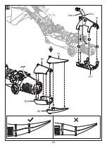
Page 29: ...2 8 B 7 B 11 B lack B 8 A4 2 0 2 2 2 1 A3 B 12 R ed ...

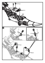
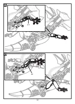
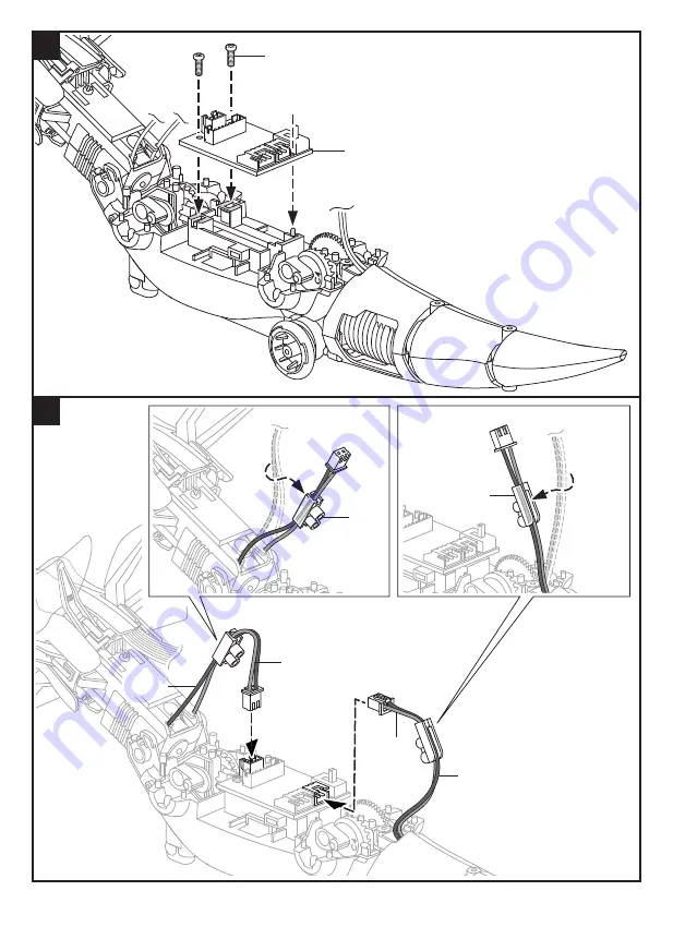
Page 30: ...P7x2 P13 2 9 2 1 2 2 C2 5 R ed B lack R ed C2 4 B lack ...

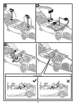
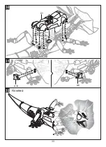
Page 31: ...30 23 24 25 1 2 Side View ...

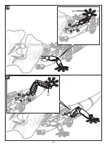
Page 32: ...31 2 6 2 7 A11 2 1 2 1 A1 ...

Page 33: ...2 8 32 A8 A2 1 2 2 9 1 2 ...

Page 34: ...D 1 33 A12 A6 3 1 3 0 F inished 3 2 ...

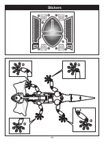
Page 35: ...S t i c k e r s 34 ...

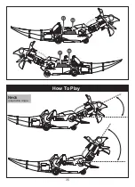
Page 36: ...How To Play 35 Neck adjustable angle ...

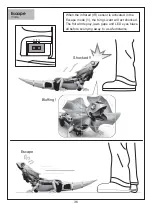
Page 37: ...ocked W hen the infrared I R sensor is activated in the Escape mode 1 the K ing L iz ard will act shocked T he frill will deploy j aws gape and L ED ey es blaz e all before scurry ing away to a safe distance 36 Escape mode ...

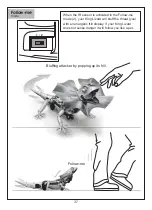
Page 38: ...ll Follow me mode F ollow me W hen the I R sensor is activated in the F ollow me mode 2 y our K ing L iz ard will bluff the threat y ou with an energetic frill display I f y our K ing L iz ard does not sense danger it will follow y ou like a pet ...

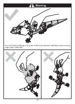
Page 39: ...U se care when handling yo ur K ing L iza rd R obot any improper handling as shown below might cause malfunction 38 W a r n i n g ...

Page 40: ......

Page 41: ...NOTES ...

Page 42: ...NOTES ...

Page 43: ...NOTES ...

Page 44: ...43500089231 ...

Reviews: