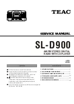
AM/FM STEREO DIGITAL
PC board shown are viewed from parts side.
The parts with no reference number or no parts number
in the exploded views are not supplied.
As regards the resistors and capacitors, refer to the
circuit diagrams contained in this manual.
Parts marked with this sign are safety critical
components. they must be replaced with identical
ensure exact replacement.
!
components - refer to the appropriate parts list and
1 SPECIFICATIONS
3 EXPLODED VIEW AND PARTS LIST
4 PC BOARDS AND PARTS LISTS
5 WIRING DIAGRAM
6 INCLUDED ACCESSORIES
2
3
16
26
28
2 ADJUSTMENT AND CHECKS
6
RADIO WITH CD PLAYER
Parts of [ ] mark can be used only with the version designated.
[E]: Europe [UK]: UK/HK
SL-D900
Summary of Contents for SL-D900
Page 8: ...5 23 20 19 15 13 14 12 7 6 17 16 2 3 1 8 18 10 22 21 21 22 4 11 9 10 SL D900 EXPLODED VIEW 2 8...
Page 10: ...1 1 SL D900 10 EXPLODED VIEW 3 2 6 7 3 4 8 5 9 10...
Page 14: ...1 6 2 8 7 3 5 4 8 9 13 11 12 10 10 EXPLODED VIEW 5 SL D900 14...
Page 17: ...MAIN PCB SL D900 17...
Page 19: ...CD PCB SL D900 19...
Page 21: ...TUNER PCB SL D900 21...
Page 23: ...CONTROL PCB SL D900 23...
Page 25: ...SL D900 25 PHONE JACK PCB AUX JACK PCB CD SW PCB BBS VR PCB SNOOZE PCB USB JACK PCB...
Page 34: ......
Page 36: ......


