


Customer Manual
取扱説明書
409-78004
Rev A
13 of 31
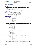
Install The Slide Pin
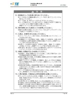
Caution
Use the Slide pin, the stopper pin, and the spring compatible with the tool. The tool may damage if
Use the Slide pin, the stopper pin, and the spring compatible with the tool. The tool may damage if
Use the Slide pin, the stopper pin, and the spring compatible with the tool. The tool may damage if
Use the Slide pin, the stopper pin, and the spring compatible with the tool. The tool may damage if
incompatible parts are applied.
incompatible parts are applied.
incompatible parts are applied.
incompatible parts are applied.
Ensure that the hole of the slide pin is not deformed or cracked. If such deformations o
Ensure that the hole of the slide pin is not deformed or cracked. If such deformations o
Ensure that the hole of the slide pin is not deformed or cracked. If such deformations o
Ensure that the hole of the slide pin is not deformed or cracked. If such deformations or cracks appear,
r cracks appear,
r cracks appear,
r cracks appear,
contact an
contact an
contact an
contact an authorized
authorized
authorized
authorized service facility.
service facility.
service facility.
service facility.
When replacing the Slide pin, remove the battery from the tool to prevent unintentional starting
When replacing the Slide pin, remove the battery from the tool to prevent unintentional starting
When replacing the Slide pin, remove the battery from the tool to prevent unintentional starting
When replacing the Slide pin, remove the battery from the tool to prevent unintentional starting
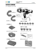
Repair parts and tool
Repair parts and tool
Repair parts and tool
Repair parts and tool
Necessary parts
Necessary parts
Necessary parts
Necessary parts
and tool to replace the slide pin are as follows
and tool to replace the slide pin are as follows
and tool to replace the slide pin are as follows
and tool to replace the slide pin are as follows
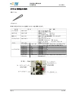
Installation procedure
Installation procedure
Installation procedure
Installation procedure
1.
1.
1.
1.
Insert the Spring and the Stopper pin coated with grease into the hole of the Cylinder head in order.
Insert the Spring and the Stopper pin coated with grease into the hole of the Cylinder head in order.
Insert the Spring and the Stopper pin coated with grease into the hole of the Cylinder head in order.
Insert the Spring and the Stopper pin coated with grease into the hole of the Cylinder head in order.
2.
2.
2.
2.
Insert the piano
Insert the piano
Insert the piano
Insert the piano wire from the hole of the Cylinder head. While pushing the Stopper pin with the Piano wire,
wire from the hole of the Cylinder head. While pushing the Stopper pin with the Piano wire,
wire from the hole of the Cylinder head. While pushing the Stopper pin with the Piano wire,
wire from the hole of the Cylinder head. While pushing the Stopper pin with the Piano wire,
insert the Slide pin coated with grease.
insert the Slide pin coated with grease.
insert the Slide pin coated with grease.
insert the Slide pin coated with grease.
3.
3.
3.
3.
Under the condition of Step 2, push the Slide pin in while pulling out the Piano wire.
Under the condition of Step 2, push the Slide pin in while pulling out the Piano wire.
Under the condition of Step 2, push the Slide pin in while pulling out the Piano wire.
Under the condition of Step 2, push the Slide pin in while pulling out the Piano wire.
4.
4.
4.
4.
Under the condition of Step 3, turn the Slide pin and place the Stopper pin into the groove
Under the condition of Step 3, turn the Slide pin and place the Stopper pin into the groove
Under the condition of Step 3, turn the Slide pin and place the Stopper pin into the groove
Under the condition of Step 3, turn the Slide pin and place the Stopper pin into the groove
5.
5.
5.
5.
Push in the Slide pin completely. Turn the Slide pin clockwise approximately 40
Push in the Slide pin completely. Turn the Slide pin clockwise approximately 40
Push in the Slide pin completely. Turn the Slide pin clockwise approximately 40
Push in the Slide pin completely. Turn the Slide pin clockwise approximately 40°
°
°
°and confirm the Slide pin is
and confirm the Slide pin is
and confirm the Slide pin is
and confirm the Slide pin is
securely locked and
securely locked and
securely locked and
securely locked and not pulling out.
not pulling out.
not pulling out.
not pulling out.
6.
6.
6.
6.
Release the lock and check insertion and extraction of the Slide pin is smooth without wobbling or pulling out
Release the lock and check insertion and extraction of the Slide pin is smooth without wobbling or pulling out
Release the lock and check insertion and extraction of the Slide pin is smooth without wobbling or pulling out
Release the lock and check insertion and extraction of the Slide pin is smooth without wobbling or pulling out
* Due to improvements to conventional parts, the external design of the Slide pin may change.
* Due to improvements to conventional parts, the external design of the Slide pin may change.
* Due to improvements to conventional parts, the external design of the Slide pin may change.
* Due to improvements to conventional parts, the external design of the Slide pin may change.
Summary of Contents for REC-Li250M
Page 16: ...Customer Manual 取扱説明書 409 78004 Rev A 16 of 31 安全上 安全上 安全上 安全上のご のご のご のご注意 注意 注意 注意 ...
Page 17: ...Customer Manual 取扱説明書 409 78004 Rev A 17 of 31 ...
Page 18: ...Customer Manual 取扱説明書 409 78004 Rev A 18 of 31 ...
Page 19: ...Customer Manual 取扱説明書 409 78004 Rev A 19 of 31 ...
Page 26: ...Customer Manual 取扱説明書 409 78004 Rev A 26 of 31 ...
Page 27: ...Customer Manual 取扱説明書 409 78004 Rev A 27 of 31 ...
Page 30: ...Customer Manual 取扱説明書 409 78004 Rev A 30 of 31 ...