


14
1.7
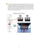
Turn on power supply to the controller (and power supply to the TE device if applicable), and set tuning
parameters as necessary. Controller tuning is discussed in section 3.
Do not mount the controller to a surface which is exposed to a source of heat, such as from
electronics, machinery, or solar radiation.
Do not cover the controller with any object or otherwise restrict natural convection airflow around
the controller. Doing so could cause the controller to overheat.
Do not mount the controller to an insulating surface. Doing so could cause the controller to
overheat.
Do not operate the controller in such a manner as to cause the surface temperature of the circuit
board or its frame to reach 70 °C. Otherwise the controller might be damaged and there might be a
risk of fire as a result.
Do not allow the controller to be exposed to water (such as from dripping or leaking water lines or
from water-vapor condensation if the surface temperature of the controller is below the dew point
temperature).
Do not allow metallic dust/shavings to contact the controller electronics.
2.0
Control Function Description
2.1
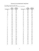
Proportional control: This eliminates much of the temperature cycling inherent in on/off control. The
proportioning bandwidth is the temperature span over which the power is proportioned from 0% to 100%
power, centered about the temperature set point. That is, the controller output decreases to 50% power as
it reaches the set point and to 0% as it reaches the end of the bandwidth range above the set point.
For example, suppose the controller is being operated in the cooling mode, the set point is 10.0 °C, and the
bandwidth is set to 5 °C. The controller power starts to proportionally decrease as the sensor temperature
cools below 12.5°C. The power will be reduced to 50% when the sensor is at 10.0 °C. Finally, the power will
be at 0% when the sensor is at 7.5°C. (Of course, this example presumes that the cooler would have
enough capacity to cool to 7.5 °C.)
If the bandwidth is set too narrow, the temperature will oscillate around the set point. If the bandwidth is
too wide, the controller will be slow to respond or may never reach set point.
2.2
Integral Control: This corrects for any offset between the set temperature and the sense temperature by
averaging the offset with respect to time. This essentially shifts the proportioning bandwidth.
For example, suppose the set temperature is 10.0 °C, the bandwidth is set to 5 °C, and the controller settled
to a constant 11.2 °C (corresponding to 74% power). If the integral control is set to 1 repeat per minute,
the controller will increase the power to 98% in 1 minute. In this example, after one minute of operation
the controller calculated that the error from the desired temperature to actual temperature was +1.2 °C
above set point. With a bandwidth of 5 °C, the controller then calculated that it needed an additional 24%
output (100% output / 5 °C * 1.2 °C = 24 %). This additional 24% output was added to the existing 74%
output to yield 98% output. The integral portion of the output is recalculated at the frequency specified by
the integral potentiometer. Thus, at the next update period for the integral the controller will add or
subtract as necessary from the 98% output. Of course, the maximum output is limited to 100% and the
minimum is limited to 0%.
If the integral control is set too high, the temperature will oscillate. If integral control is set too low, it will
take a long time for the temperature to settle to steady state.


