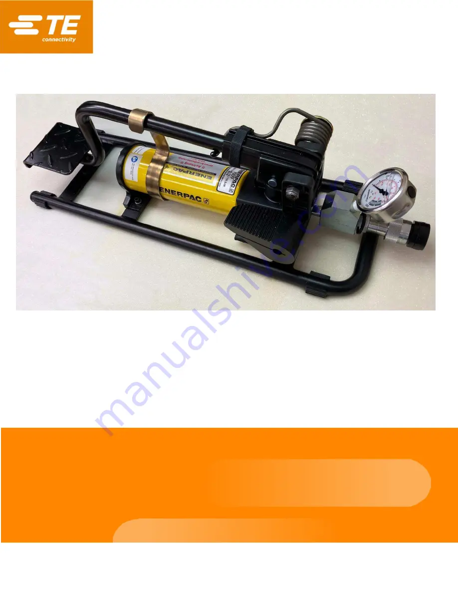
TE 523199-3 Hydraulic Foot Pump
Part number 523199-3
Customer Manual
409-35036
5 JUN 2023 Rev A
Original instructions
Page 1: ...TE 523199 3 Hydraulic Foot Pump Part number 523199 3 Customer Manual 409 35036 5 JUN 2023 Rev A Original instructions...
Page 2: ...ctions Many difficulties can be avoided in this manner When calling the Support Center be ready with the following information Customer name Customer address Person to contact name title telephone num...
Page 3: ...tion 10 5 1 Before using the pump 10 5 2 Using a two speed pump 10 5 3 Single acting application with a release valve 11 6 Maintenance 12 6 1 Removing air 12 6 2 Hydraulic fluid 13 6 2 1 Keeping the f...
Page 4: ...ed these warnings could result in severe injury from harmful fumes or burns from flying debris CAUTION Do not perform any service or maintenance other than as described in this manual Injury or damage...
Page 5: ...s with inches in brackets Figures are for reference only and are not drawn to scale Figure 1 Pump dimensions NOTE The height of the lever when raised is 433 mm 17 05 Table 1 Specifications Specificati...
Page 6: ...gauge 8 Release valve handle The pump is used to actuate hydraulic crimping heads that operate at a pressure of 8 000 to 8 400 psi 552 to 579 bar only Use hydraulic hose assembly 523237 8 Table 2 8 20...
Page 7: ...r a maximum pressure of 700 bars The nominal pressure is set to 565 bar Do not connect a cylinder to a pump with a higher pressure rating DANGER To prevent over pressurizing the system the pump is equ...
Page 8: ...Connections must be secure and leak free Overtightening can cause permanent thread failure or cause high pressure fittings to split at pressures lower than their rated capacities These failures can c...
Page 9: ...oose ends from the tape Leave the first thread free of tape so that it does not shed into the hydraulic system 2 Insert the male coupling of the hydraulic hose into the female coupling on the pump 3 T...
Page 10: ...roke 5 1 Before using the pump 1 Verify that all system fittings and connections are tight and free of leaks 2 Check the fluid level in the reservoir Add hydraulic fluid if necessary see section 6 2 5...
Page 11: ...tools on the release valve handle Doing so can damage the pump and cause it to malfunction Figure 5 Closing the release valve 2 Operate the lever to generate hydraulic power for the system The pressu...
Page 12: ...vented pumps only 2 Close the release valve see Figure 5 3 Position the pump at a higher elevation than the crimping head Figure 6 Figure 6 Removing air 1 Air 2 Direction of air flow 4 Position the c...
Page 13: ...acted extended if using a pull cylinder Failure to do so forces more fluid into the reservoir than it can hold This can rupture the casing causing injury and equipment damage 1 Remove the fill cap Fig...
Page 14: ...ing fluid from flowing out of the pump 4 Remove air from the system if needed see section 6 1 5 Verify that the fluid level is still correct 6 Reinstall the fill cap 7 Dispose of the used fluid as req...
Page 15: ...rnal leakage in pump Contact TE for service section 8 Cylinder retracts slowly partly or not at all Release valve is closed Open the valve Overfilled reservoir Drain fluid to fill line Figure 7 Loose...