


AN-000158
Document Number: AN-000158
Page 14 of 22
Revision: 1.2
PIF ACOUSTIC PERFORMANCE IMPACT AND INSERTION LOSSES
The SAATI Acoustex B042HY has one-way insertion loss of 3 dB. This implies a 6 dB total insertion loss in use with the sensor,
because the insertion loss applies during both transmit and receive.
PIF Material
IP Rating
Insertion Loss (Round-trip)
SAATI Acoustex B042HY
IP5X
6 dB
Table 5. Acoustic insertion loss of PIF materials on sensor.
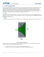
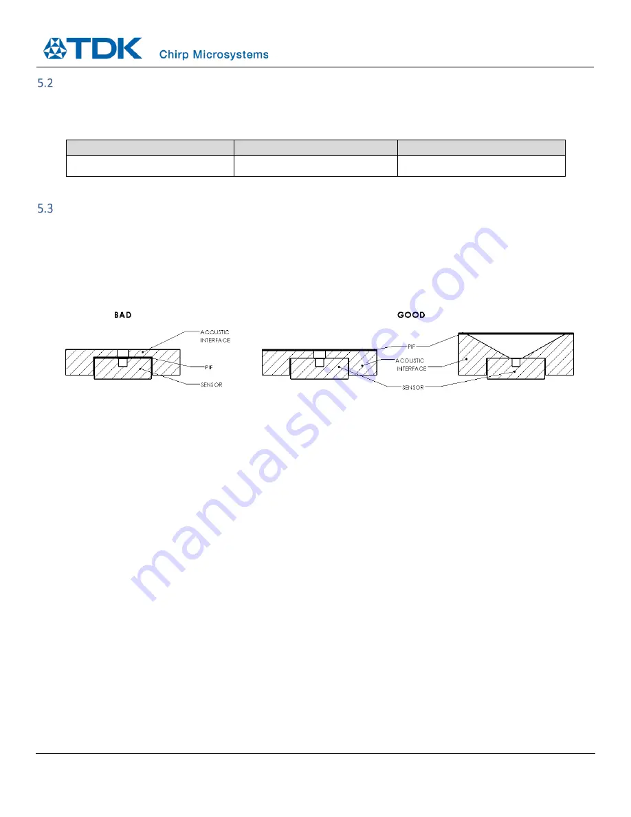
PIF PLACEMENT
For the CH101 and ICU-10201, the PIF must be placed in a specific position in the acoustic path between the sensor PMUT and the
air. Chirp’s testing has shown that PIFs placed directly on
top of the sensor package and right over the port hole generally
significantly decrease acoustic performance. Placing the PIF for the sensor at the top of the Acoustic Interface is recommended.
Chirp has validated this placement for the SAATI Acoustex B042HY. The optimal PIF placement for any other PIF other than the SAATI
Acoustex B042HY is not guaranteed. Please contact Chirp for more information.
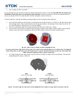
Figure 13. Examples of bad vs good PIF placement.
Bad PIF placement (left) is when the PIF is placed directly on top of the sensor package. Good PIF placement involves placing it on top of the
Acoustic Interface. This applies for both tubes (middle) and horns (right).


