TMN-5000i-V1
TMN-5000i Hardware User Manual (Ver.1)
8
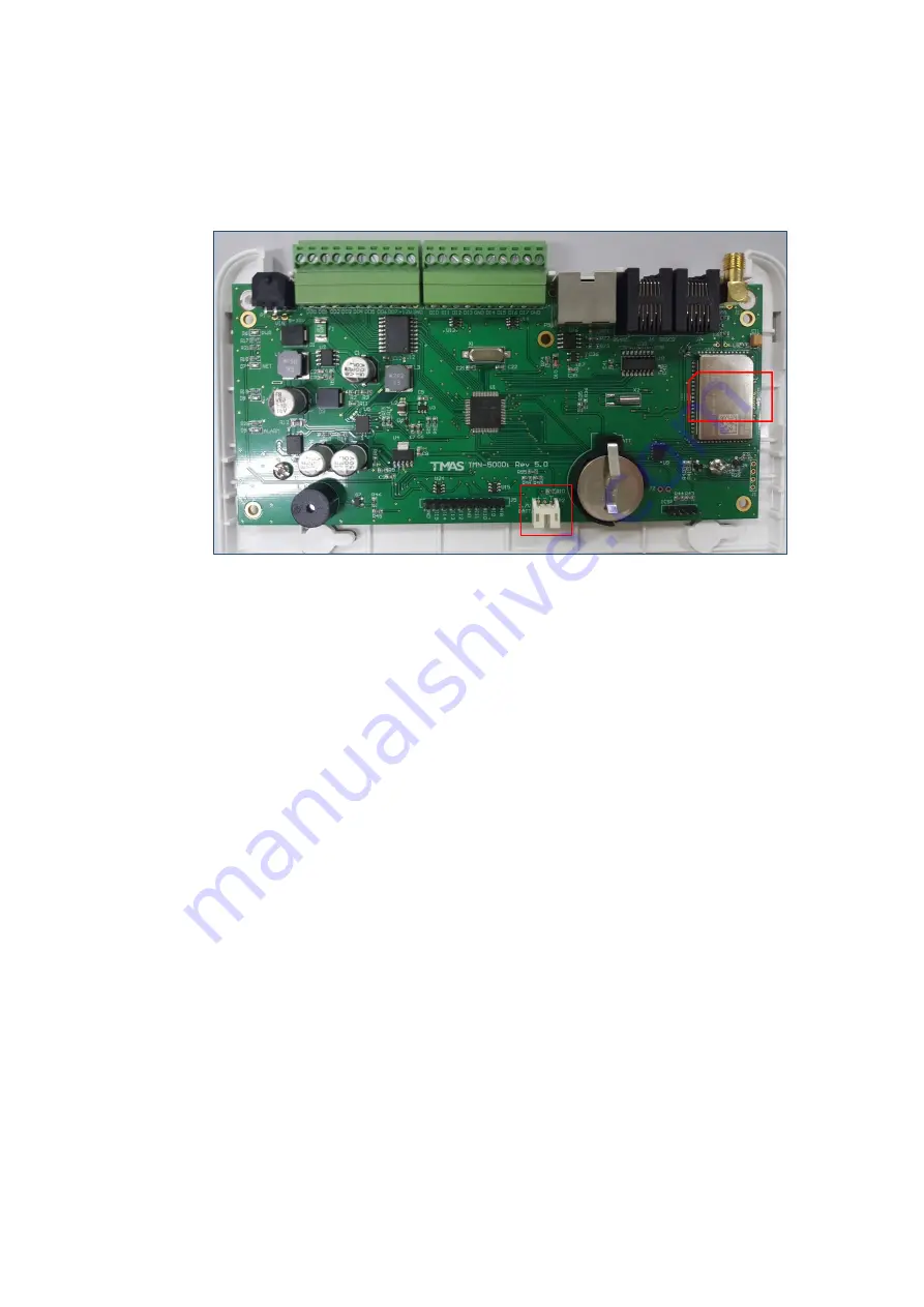
Next, locate the SIM card holder which is underneath the printed circuit board (as shown
below in the Figure 8). Insert your SIM card with its chip facing up. Push it inward until you
hear a click sound.
Figure 8 Locations of the SIM Card Holder and Backup Battery Power Socket
To extract your SIM card, push it inward again until you hear a click sound, and then
release your finger.
6.2
Step 2: Connect Backup Battery
In case of power failure, TMN-5000i is equipped with a backup battery to sustain its
operation. Assuming no external devices are connected to the TMN-5000i, the backup
battery is estimated to last for minimum 4 hours on standby. You may locate a white-
coloured backup battery power socket as shown above in the Figure 8, and plug it with
the battery connector cable.
6.3
Step 3: Connect Input/ Output (I/O)
The input terminals work with +5V TTL or voltage-free dry contact digital input. All input
channels can be configured by TMAS PC Manager Software to select either normally
open (NO) or normally closed (NC) sensor type.
To check for the I/O terminals, please refer to Appendix A. You can connect your input
device to any digital input. Use a flat screwdriver to drive the screw up and insert the hot
wire of your input device. Next, drive the screw down to tighten it. Connect the ground
wire of your input device to the ground terminal.


