background image

 9

Models 8752, 8756, 8757

Operator Parts Identification

160630

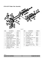
8752 Beater Door Assembly

Figure 2 

ITEM

DESCRIPTION

PART NO.

1

SEAL-DRIVE SHAFT

032560

2

SHAFT-BEATER

032564

3

BEATER A.-3.4QT-1 PIN

X46231

4

BLADE-SCRAPER-PLASTIC

046235

5

KIT A.-BEATER-FRONT

SHOES-BEARING (6a-6c)

X50350

6

GASKET-DOOR HT 4"-DOUBLE

048926

7

DOOR A.-1 SPOUT

X51531-10

7a

BAFFLE A.-LONG 4 IN

X50882

8

HANDLE A.-DRAW-ADJ.

X55096

8a

HANDLE-ADJUSTABLE

028804

8b

SCREW-ADJUSTMENT

055092

ITEM

DESCRIPTION

PART NO.

8c

O-RING-1/4 OD X .070W 50

DURO (25 TO BAG)

015872

8d

NUT-JAM

029639-BLK

9

O-RING-5/16 OD X .070W 

(50 TO BAG)

016272

10

PIN A.-PIVOT

X22820

11

NUT-STUD

021508

12

VALVE A.-DRAW

X18303

13

O-RING-7/8 OD X .103W 

(100 TO BAG)

014402

14

CAP-DESIGN-1.010"ID-6 POINT

014218

15

PLUG-PRIME

028805

16

O-RING-3/8 OD X .070W 

(100 TO BAG)

016137

Summary of Contents for Horizon 8752

Page 1: ...OPERATOR S MANUAL Model 8752 8756 8757 Soft Serve Freezers Original Operating Instructions 028752 M 8 99 Original Publication Updated 7 1 16...

Page 2: ...city Amps Part Number E 1999 Taylor Company 028752 M Any unauthorized reproduction disclosure or distribution of copies by any person of any portion of this work may be a violation of Copyright Law of...

Page 3: ...ater Door Assembly 14 Accessories 15 Section 5 Important To the Operator 16 Symbol Definitions 17 Power Switch 17 Indicator Lights MIX LOW and MIX OUT 17 Reset Button 17 SOFTECH Control Operation 17 M...

Page 4: ...Continuing research results in steady improvements therefore information in this manual is subject to change without notice Note Only instructions originating from the factory or its authorized transl...

Page 5: ...damage to the equipment Note All repairs must be performed by an authorized Taylor Service Technician This unit has many sharp edges that can cause severe injuries Site Preparation Review the area whe...

Page 6: ...or safety In all other areas of the world equipment should be installed in accordance with the existing local codes Please contact your local authorities FOLLOW YOUR LOCAL ELECTRICAL CODES Each unit r...

Page 7: ...the right and left sides for the Models 8756 and 8757 Refrigerant In consideration of our environment Taylor proudly uses only earth friendly HFC refrigerants The HFC refrigerant used in this unit is...

Page 8: ...uct is compliant with the EU Directive as well as other similar legislation in effect after August 13 2005 Therefore it must be collected separately after its use is completed and cannot be disposed a...

Page 9: ...zed installer The installation location is marked by the equipotential bonding symbol 5021 of IEC 60417 1 on both the removable panel and the equipment s frame DO NOT use a water jet to clean or rinse...

Page 10: ...must be placed on a level surface Failure to comply may result in personal injury or equipment damage Access to the service area of the unit is restricted to persons having knowledge and practical ex...

Page 11: ...7 Models 8752 8756 8757 Operator Parts Identification 160630 Section 4 Operator Parts Identification Figure 1...

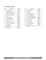
Page 12: ...IP 11 5 8 LONG 027503 11 CASTER 3 SWV 3 4 10 STEM 021279 12 GASKET MIX DOOR 020134 13 PROBE A MIX W BALL CONNECTORS X35981 14 BOOT COVER MIX 037200 ITEM DESCRIPTION PART NO 15 TANK MIX 15 GALLON 02027...

Page 13: ...DOUBLE 048926 7 DOOR A 1 SPOUT X51531 10 7a BAFFLE A LONG 4 IN X50882 8 HANDLE A DRAW ADJ X55096 8a HANDLE ADJUSTABLE 028804 8b SCREW ADJUSTMENT 055092 ITEM DESCRIPTION PART NO 8c O RING 1 4 OD X 070...

Page 14: ...10 Models 8752 8756 8757 Operator Parts Identification 160630 Model 8756 Figure 3...

Page 15: ...3 4 10 STEM 021279 12 GASKET CAB MIX DOOR 024629 13 PROBE A MIX W BALL CONNECTORS X35981 14 BOOT COVER MIX 037200 15 TANK A MIX W DECALS X38755 SER ITEM DESCRIPTION PART NO 15a TANK MIX 9 GALLON 0349...

Page 16: ...12 Models 8752 8756 8757 Operator Parts Identification 160630 Model 8757 Figure 4...

Page 17: ...r Swivel 3 4 10 ST 021279 12 Gasket Cabinet Mix Door 024629 13 Probe A Mix X35981 14 Boot Mix Cover 037200 15 Tank Mix X38755 15a Tank only 034928 Item Description Part No 16 Cover Mix Tank 024590 17...

Page 18: ...RAD X50882 8 HANDLE A DRAW 9a 9c X81010 SP 8a HANDLE A ADJ THREADED X80889 SP 8b SCREW ADJUSTMENT 5 16 24 056332 8c O RING 1 4 OD X 070W 50 DURO 25 TO BAG 015872 9 O RING 5 16 OD X 070W 50 TO BAG 0162...

Page 19: ...072 5 BRUSH REAR BRG 1 X 2 X 14 013071 6 BRUSH DRAW VALVE 1 X 2X17 013073 7 BRUSH SET LVB 050103 8 LUBRICANT TAYLOR 4 OZ 047518 ITEM DESCRIPTION PART NO 9 SANITIZER STERA SHEEN SEE NOTE 10 PAIL 10 QT...

Page 20: ...16 Models 8752 8756 8757 Important To the Operator 160324 Section 5 Important To the Operator Model 8752 Figure 7...

Page 21: ...ally begin operation Reset Button The reset button is located in the decorative plate above the SOFTECH controls The reset protects the beater motor from an overload condition Should an overload occur...

Page 22: ...nctions are automatically cancelled The MIX REF function is automatically locked in to maintain the mix in the cabinet and the PUMP function is locked in to allow air mix pump operation as required Pu...

Page 23: ...is filled to the indicating mark on the bottom of the well The heated rail should have 32 ounces 946 2 ml of water Step 2 Place the heater switch in the ON position Note This heating process will take...

Page 24: ...any signs of wear or damage If a scraper blade is nicked or worn replace both blades Figure 10 Step 4 If the blades are in good condition place the rear scraper blade over the rear holding pin on the...

Page 25: ...bearing s over the baffle rod s making certain that the flanged end of the bearing is resting against the freezer door DO NOT lubricate the gasket s or front bearing s Figure 13 Note There are two gas...

Page 26: ...ot in the draw valve s comes into view Figure 18 Step 16 Install the adjustable draw handle s Slide the o ring s into the groove s on the pivot pin s and lubricate Figure 19 Step 17 Slide the fork of...

Page 27: ...controlling costs The draw handles can be adjusted for different flow rates See page 18 for more information on adjusting these handles Step 18 Snap the design cap over the bottom of each door spout...

Page 28: ...y defective parts immediately and discard the old Step 2 Assemble the piston Slide the o ring into the groove on the piston DO NOT lubricate this o ring Figure 24 Step 3 Assemble the liquid valve body...

Page 29: ...de the o ring into the groove on the mix inlet fitting and lubricate with Taylor Lube Figure 29 Attach the spring and poppet to the end of the mix inlet fitting above the o ring The spring must be sec...

Page 30: ...ing the tubing Attach one end of the flare line to the threaded fitting on the lower side of the pump cylinder and allow the other end to hang free Figure 34 Step 8 Secure the air mix pump Place the p...

Page 31: ...sides of the pressure switch diaphragm Figure 38 Step 10 Place the diaphragm on the front face of the pressure switch housing The lubricant will act as an adhesive to hold the diaphragm in place Note...

Page 32: ...13 16 OD X 139W 50 TO BAG 021278 3h ELBOW INLET 90 DEG 022502 4 3i SPRING TAPERED 1 7 8L 022456 3j POPPET RUBBER BLACK 022473 3k RING CHECK 1 1 4 OD X 3 8 033215 3l O RING 1 3 8 OD X 103W 123 50 TO B...

Page 33: ...the mix inlet tube with the long brush and sanitizing solution Figure 41 Step 3 Connect the free end of the flare line to the threaded fitting on the mix inlet tube Figure 42 Step 4 Install the pressu...

Page 34: ...l stop operation Figure 45 Step 8 Drain and connect the free end of the pressure line to the pressure switch Figure 46 Step 9 Place an empty pail beneath the door spout and raise the prime plug Figure...

Page 35: ...tion may result in damage to the freezing cylinder Note On the Models 8756 and 8757 momentarily pull down the center draw handle to sanitize the center door spout Step 12 Repeat Steps 1 through 11 for...

Page 36: ...e plug hole push down the prime plug Rinse the prime plug hole area with water Remove the pail and discard the mix and the sanitizer Figure 54 IMPORTANT Failure to remove all sanitizing solution may r...

Page 37: ...n the Models 8756 and 8757 ALWAYS FOLLOW LOCAL HEALTH CODES Rinsing Step 1 Fill the empty pail in the mix cabinet with 2 gallons 7 6 liters of cool clean water Place the free end of the suction line i...

Page 38: ...pin out of the pump collar and slide the collar down Tilt the air mix pump away from the machine and take the entire assembly to the sink for further disassembly and brush cleaning Step 3 Remove the...

Page 39: ...del 8757 the following items will be needed Digital thermometer with needle probe calibrating cup flatblade screwdriver sanitizer examples Stera Sheen or Kay 5 Note This procedure should be performed...

Page 40: ...n the sides of the cup Note The amount of dispensed topping should be one fluid ounce 29 6 ml 12 If the dispensed amount is correct proceed to Step 13 If the amount of dispensed topping is not correct...

Page 41: ...nitized covered stainless steel container and is used the following day DO NOT prime the machine with rerun When using rerun skim off the foam and discard then mix the rerun with fresh mix in a ratio...

Page 42: ...re worn torn or fit too loosely and replace with new ones 2 Follow lubricating procedures carefully NEVER lubricate check bands 3 Handle plastic pump parts with care to avoid nicks and cracks 4 Be sur...

Page 43: ...ve all the way up to remove restriction Never put objects or fingers in door spout g Machine is unplugged g Plug machine into the wall receptacle h Circuit breaker is off or the fuse is blown h Turn t...

Page 44: ...a service technician to replace the pressure switch h Pressure switch diaphragm installed incorrectly or missing h Diaphragm must be correctly installed in the pressure switch cap or the housing 27 i...

Page 45: ...ers Minimum of 3 7 6 cm clearance on all sides Do not obstruct air discharge on top 12 30 5 cm clearance on top of freezer 1 5 Mix in the mix cabinet is too warm a Warm mix was placed in the tank a Mi...

Page 46: ...e gear box b Rounded corners on hex end of drive shaft or gear coupling b Replace damaged component 10 The freezing cylinder walls are scored a The scraper blades are damaged a Replace the scraper bla...

Page 47: ...ust be correctly installed in the pressure switch cap or the housing 27 12 The machine will not operate in the AUTO mode a The machine is unplugged a Plug the machine into the wall receptacle b The ci...

Page 48: ...ing O Ring X 1 Pressure Switch Diaphragm X 1 Design Cap X 1 White Bristle Brush 9 16 x 44 Inspect Replace if Necessary Minimum 1 White Bristle Brush 1 x 2 Inspect Replace if Necessary Minimum 1 White...

Page 49: ...rvice valve Five 5 years Beater motors Two 2 years Beater drive gear Two 2 years Printed circuit boards and Softech controls beginning with serial number H8024200 Two 2 years Parts not otherwise liste...

Page 50: ...reason whatsoever 12 Damages resulting from the use of any refrigerant other than that specified on the Product s data label will void this limited warranty 13 Any cost to replace refill or dispose o...

Page 51: ...12 Parts Twelve 12 months Class 000 Parts No warranty Taylor Part 072454 Motor 24VDC C832 C842 Four 4 years LIMITED WARRANTY CONDITIONS 1 If the date of original installation of the Part cannot be oth...

Page 52: ...rvice work promptly upon arrival 9 Failure damage or repairs due to faulty installation misapplication abuse no or improper servicing unauthorized alteration or improper operation or use as indicated...

Page 53: ...DAMAGES INCLUDING CLAIMS FOR LOST SALES LOST PROFITS PRODUCT LOSS PROPERTY DAMAGES OR SERVICE EXPENSES ARE EXPRESSLY EXCLUDED THE EXPRESS WARRANTIES MADE IN THIS LIMITED WARRANTY MAY NOT BE ALTERED EN...

Reviews: