

Section 6
6-1
Model C303 & C314
Operating Procedures
6
Operating Procedures
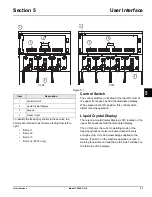
The Model C303 has been selected to illustrate the
pictured step-by-step operating procedures for both
models contained in this manual. These models, for
practical purposes of operation, are the same.
Note:
The Model C303 contains three 7 quart (6.6 liter)
freezing cylinders. The Model C314 contains four 7 quart
(6.6 liter) freezing cylinders.
WARNING!
This unit is pressurized when in
operation.
•
The control switch must be in the OFF position
until the unit is completely assembled.
•
No part should ever be removed from the
machine while it is in operation.
•
No parts should be removed until the control
switch has been turned to the OFF position and
all pressure has been relieved by opening the
draw valve.
Failure to follow this instruction may result in severe
personal injury from hazardous moving parts or from the
impact of propelled parts.
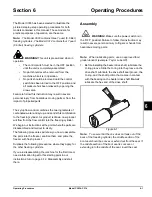
The syrup flow control combines the two ingredients of
carbonated water and syrup, and sends this combination
to the freezing cylinder. As product is drawn, new product
will flow from the flow control into the freezing cylinder.
We begin our instructions at the point where the parts are
disassembled and laid out to air dry.
The following procedures will show you how to assemble
the parts into the freezer, sanitize them, and prime the
freezer with fresh product.
Duplicate the following procedures, where they apply, for
the other freezing cylinders.
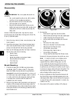
If you are disassembling the machine for the first time or
need information to get to this starting point in our
instructions, turn to page 6-12, Disassembly and start
there.
Assembly
WARNING!
Make sure the power switch is in
the “OFF” position! Failure to follow this instruction may
result in severe personal injury to fingers or hands from
hazardous moving parts.
Note:
When lubricating parts, use an approved food
grade lubricant (example: Taylor Lube HP).
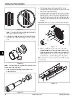
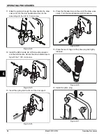
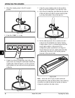
1. Before installing the beater drive shaft, lubricate the
O-ring groove. Slide the O-ring into the groove on the
drive shaft. Lubricate the drive shaft seal groove, the
O-ring, and the shaft portion that comes in contact
with the bearing on the beater drive shaft.
Do not
lubricate the hex end of the drive shaft.
Figure 6-1
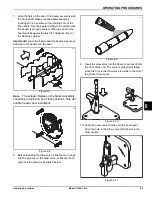
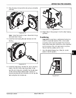
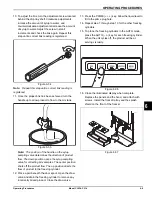
Note:
To ensure that the mix does not leak out of the
back of the freezing cylinder, the middle section of the
boot seal should be convex or extend out from the seal. If
the middle section of the boot seal is concave or
extending into the middle of the seal, invert the seal
Summary of Contents for C303
Page 14: ...3 4 SAFETY Model C303 C314 Safety 3 Notes...
Page 41: ...OPERATING PROCEDURES 6 13 Model C303 C314 Operating Procedures 6...
Page 43: ...7 2 OPERATOR CHECKLIST Model C303 C314 Operator Checklist 7 Notes...
Page 47: ...9 2 PARTS REPLACEMENT SCHEDULE Model C303 C314 Parts Replacement Schedule 9 Notes...
Page 53: ...11 4 LIMITED WARRANTY ON PARTS Model C303 C314 Limited Warranty on Parts 11 Notes...


