


Drive Axle-GT
Page 43
MB-210-13
B-200 & B-210 Models
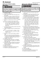
SECONDARY GEAR CASE
Disassemble
1: Remove the transaxle assembly from the vehicle.
Refer to Remove in this section.
2: Place a drain pan under the gear case that is
capable of holding 4 liters (4 quarts) of oil and
drain the oil from the front and secondary gear
case.
3: Place the axle assembly on an appropriate stand.
4: Remove the axle shafts and tubes as an
assembly by removing the six axle tube flange
bolts on each axle tube.
5: Remove the primary reduction gear case.
Refer to Primary Gear Case for information on
removing the gear case.
6: Remove the 12 side plate bolts, then remove the
side plate.
7: Remove the carrier bearing adjusting nut roll pin
and adjusting nut from the side
plate.
8: Turn the side plate over and
remove the carrier bearing race
from the side plate.
9: Remove the differential assembly.
10: Remove the carrier bearing
adjusting nut roll pin from the
carrier housing, then remove the
carrier adjusting nut.
11: Remove the carrier bearing race
from the 3rd member housing.
12: Remove the front bearing from the pinion gear
shaft.
Note: The pinion gear may have to be driven out
to perform this procedure.
13: Remove the pinion gear shims and spacer.
14: Remove the pinion gear from the carrier housing.
15: Remove the front and rear pinion bearing races.
16: Inspect all parts for signs of wear or damage.
17: Thoroughly clean all parts.
This section is one section of a complete service
manual. Before starting any procedure, read all
warnings and instructions that are located in the
Service Guidelines chapter.
WARNING
Assemble
1: Temporarily install the pinion gear (hand tighten
only).
2: Install the carrier bearing race adjusting nuts into
the housing and cover.
3: Install the carrier bearing races into the housing
and cover.
4: Place the differential assembly into the housing.
5: Tighten the housing carrier bearing race adjusting
nut so that the ring gear is not in binding against
the pinion gear.
6: Remove the differential assembly.
Note: Do not allow the ring nut to rotate.
7: Remove the pinion gear and then reinstall the
differential assembly.
8: Install the cover onto the housing using 4-bolts in
a cross pattern and torque per torque listed in the
Hardware Torque table at the end of this section.
9: Pre set the carrier bearing preload by tightening
the housing carrier bearing race adjusting nut
until it requires 2.1 - 4.7 Nm (1.5 to 3.3 foot
pounds) to rotate the differential assembly.
Note: Rotate the carrier assembly whenever
adjusting the ring nuts.
10: Mark the position of each carrier bearing
adjusting nut in relation to the drive housing and
cover and then remove the differential assembly,
do not allow the nuts to rotate.
11: Install the pinion gear. Re-shim if required. Refer
to Pinion Bearing Preload procedure.
12: Install the pinion gear holding tool (96-500-42)
and tighten the pinion nut enough to keep the
pinion gear from rotating.
Roll Pin
Pinion Holding Tool
Summary of Contents for B0-210-36
Page 6: ......
Page 12: ...Page 12 MB 210 13 Introduction B 200 B 210 Models Notes...
Page 28: ...Lubrication Page 28 B 200 B 210 Models MB 210 13 Notes...
Page 53: ...Transaxle Page 53 MB 210 13 B 200 B 210 Models...
Page 62: ...Drive Axle Page 62 B 200 B 210 Models MB 210 13 Notes...
Page 71: ...Steering Page 71 MB 210 13 B 200 B 210 Models Exploded View of Steering Gear...
Page 81: ...Brakes Page 81 MB 210 13 B 200 B 210 Models...
Page 118: ...Tires Wheels Page 118 B 200 B 210 Models MB 210 13 Notes...
Page 130: ...Replacement Parts Page 130 MB 210 13 B 200 B 210 Models AXLE ASSEMBLY FRONT...
Page 134: ...Replacement Parts Page 134 MB 210 13 B 200 B 210 Models TRANSAXLE ASSEMBLY B 200...
Page 136: ...Replacement Parts Page 136 MB 210 13 B 200 B 210 Models TRANSAXLE ASSEMBLY B 210 REAR GT...
Page 140: ...Replacement Parts Page 140 MB 210 13 B 200 B 210 Models BATTERY...
Page 142: ...Replacement Parts Page 142 MB 210 13 B 200 B 210 Models BRAKES BRAKE LINES...
Page 144: ...Replacement Parts Page 144 MB 210 13 B 200 B 210 Models BRAKES MASTER CYLINDER LINKAGE...
Page 148: ...Replacement Parts Page 148 MB 210 13 B 200 B 210 Models BRAKES B 200 REAR AXLE...
Page 150: ...Replacement Parts Page 150 MB 210 13 B 200 B 210 Models BRAKES B 200 PARK BRAKE...
Page 152: ...Replacement Parts Page 152 MB 210 13 B 200 B 210 Models BRAKES B 210 PARK BRAKE...
Page 159: ...Replacement Parts Page 159 Not available at time of printing MB 210 13 B 200 B 210 Models...
Page 160: ...Replacement Parts Page 160 MB 210 13 B 200 B 210 Models DECALS...
Page 162: ...Replacement Parts Page 162 MB 210 13 B 200 B 210 Models ELECTRICAL MISCELLANEOUS...
Page 166: ...Replacement Parts Page 166 MB 210 13 B 200 B 210 Models FRAME DOORS...
Page 170: ...Replacement Parts Page 170 MB 210 13 B 200 B 210 Models FRAME AMBULANCE DECK...
Page 172: ...Replacement Parts Page 172 MB 210 13 B 200 B 210 Models FRAME TOPS...
Page 180: ...Replacement Parts Page 180 MB 210 13 B 200 B 210 Models STEERING COLUMN...
Page 186: ...Replacement Parts Page 186 MB 210 13 B 200 B 210 Models Notes...


