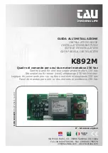
tau K892M Installation Manual Download Page 1

1

K892M

GUIDA ALL’INSTALLAZIONE

INSTALLATION GUIDE

INSTALLATIONSANLEITUNG

NOTICE D’INSTALLATION

GUÍA PARA LA INSTALACIÓN

K892M

Quadro di comando per uno/due motori monofase 230 Vac 

Control panel for one-two single-phase motors 230 Vac

Steuerplatine für einen (zwei) einphasige 230 Vac Motoren

Logique de commande pour un ou deux moteurs monophasés 230 Vac

Panel de mandos para uno or dos motores monofásicos 230 Vac

Via Enrico Fermi, 43 - 36066 Sandrigo (VI) Italia

Tel +39 0444 750190 - Fax +39 0444 750376

[email protected] - www.tauitalia.com

IT - Istruzioni originali

D-MNL0K892M

 30-07-2019 - rev

.19

Summary of Contents for K892M

Page 1: ...l for one two single phase motors 230 Vac Steuerplatine für einen zwei einphasige 230 Vac Motoren Logique de commande pour un ou deux moteurs monophasés 230 Vac Panel de mandos para uno or dos motores monofásicos 230 Vac Via Enrico Fermi 43 36066 Sandrigo VI Italia Tel 39 0444 750190 Fax 39 0444 750376 info tauitalia com www tauitalia com IT Istruzioni originali D MNL0K892M 30 07 2019 rev 19 ...

Page 2: ...GRAM SCHALTPLAN DER DL6 DL7 DL1 DL2 DL3 DL4 DL8 DL5 Close Resistive sensitive edge Fixed safety edge Common Outp 24V A Common Stop O C PIN5 FCA PIN4 FCC PIN3 GND PIN2 O C PIN1 STOP Cap 16µF Cap 16µF Common Open Close Common DIP 10 ON DIP 10 OFF Open ...

Page 3: ... CABLEADO K892M O C Open Close Cap Capacitor TX Transmitter RX Receiver FCA Open limit switch FCC Close limit switch M Motor Output 24V AC 2 Ch RX Aerial Courtesy light 230V AC Flashing light 230V AC max 20W Power selector RCM 230V AC Power supply ...

Page 4: ...rettive CEE 2014 35 EU Direttiva Bassa Tensione 2014 30 EU Direttiva Compatibilità Elettromagnetica ed ove richiesto alla Direttiva 2014 53 EU Apparecchiature Radio e apparecchiature terminali di telecomunicazione Dichiara inoltre che non è consentito mettere in servizio il macchinario fino a che la macchina in cui sarà incorporato o di cui diverrà componente sia stata identificata e ne sia stata ...

Page 5: ...f fettuati solo da personale professionalmente qualificato in conformità a quanto previsto dalle leggi norme o direttive vigenti Nella progettazione delle proprie apparecchiture TAU rispetta le normative applicabili al prodotto ve dere la dichiarazione di conformità allegata è fondamentale che anche l installatore nel realizzare gli impianti prosegua nel rispetto scrupoloso delle norme Personale n...

Page 6: ...urante la programmazione del radiocomando CARATTERISTICHE TECNICHE Alimentazione scheda 230V AC 50 Hz Potenza nominale max motori 400 W Fusibile rapido protezione ausiliari 24 V ac F1 5x20 F 500 mA Tensione circuiti alimentazione motore 230V AC Tensione alimentazione circuiti dispositivi ausiliari 24V AC Fusibile rapido protezione alimentazione ingresso 230 Vac F2 5x20 F 6 3 A Temperatura di funzi...

Page 7: ...tatto N A Normalmente Aperto per le modalità d uso vedi le funzioni dei dip switch nr 2 3 16 Comune 18 Apre Chiude 19 20 21 MOTORE 1 uscita motore 1 19 fase chiusura 20 comune 21 fase apertura 22 23 24 MOTORE 2 uscita motore aggiunto 2 22 fase chiusura 23 comune 24 fase apertura M5 STOP APRE CHIUDE FCC FCA PIN1 Ingresso pulsante STOP PIN2 Ingresso pulsante APRE CHIUDE PIN3 Comune GND PIN4 Ingresso...

Page 8: ...sione con DIP4 in ON e tempo di lavoro non memorizzato si attiva la procedura di setup della corsa Il led DL7 lampeggia velocemente PROCEDURA SENZA FINECORSA INSTALLATI 1 Premere il tasto AP CH per far partire in chiusura l anta dell automazione 2 Quando l anta risulta chiusa premere il tasto AP CH L automazione inverte la marcia e inizia un apertura 3 Premere AP CH quando si vuole che inizi il ra...

Page 9: ...i comando CH2 morsetti nr 9 e 10 è inserita Off la funzione bistabile o PASSO PASSO del relè di comando CH2 mor setti nr 9 e 10 è inserita 7 On con il dip switch 6 in ON funzione monostabile il contatto N A rimane chiuso per 180 sec tempo fisso non variabile per il comando temporiz zato delle luci Off con il dip switch 6 in ON funzione monostabile il contatto N A rimane chiuso per 2 sec tempo fiss...

Page 10: ...isso 1 3 del TL No ENCODER FC opzionali Tempo chiusura automatica Tempo di lavoro Non usato ON ON Rallentamento a tempo regolabile TL fisso 48 sec ENCODER necessario FC necessari Tempo chiusura automatica Tempo di rallentamento Sensibilità encoder SOFTWARE Versione 3 10 e successive Tabella 2 DIP 4 DIP 8 Modalità impostata TM1 TCA TM2 TL TM3 FR OFF OFF Nessun rallentamento No ENCODER FC opzionali ...

Page 11: ... che la modalità di cancellazione è attivata 3_ tenere pemuto nuovamente il tasto P1 per 3 secondi 4_ il led DL7 si spegne per 3 secondi ca per poi riaccendersi fisso ad indicare l avvenuta cancella zione 5_ riprendere la procedura dal punto 1 utilizzando il tasto P2 per cancellare tutti i radiocomandi ad esso associati 6_ se si desidera uscire dalla modalità di cancellazione senza memorizzare un ...

Page 12: ...anzia comprende la riparazione con sostituzione gratuita franco sede TAU spese di imballo e di trasporto sono a carico del cliente delle parti che presentano difetti di lavorazione o vizi di materiale riconosciuti dalla TAU In caso di intervento a domicilio anche nel periodo coperto da garanzia l utente è tenuto a corrispon dere il Diritto fisso di chiamata per spese di trasferimento a domicilio p...

Page 13: ...ge Directive 2014 30 EU Electromagnetic Compatibility Directive and where required with the Directive 2014 53 EU Radio equipment and telecommunications terminal equipment Also declares that it is not permitted to start up the machine until the machine in which it is incorporated or of which it will be a component has been identified with the relative declaration of conformity with the provisions o...

Page 14: ...formity This product may only be installed and serviced by qualified personnel in compliance with current laws regulations and directives When designing its products TAU observes all applicable standards please see the attached decla ration of conformity but it is of paramount importance that installers strictly observe the same stand ards when installing the system Unqualified personnel or those ...

Page 15: ...AL CHARACTERISTICS Power input to board 230V AC 50 Hz Max motors nominal power 400 W Fast acting fuse for protection of auxiliary circuits 24 V dc F1 5x20 F 500 mA Input voltage of motor circuits 230V AC Input voltage of auxiliary circuits 24V AC Fast acting fuse for protection of input power supply 230 Vac F2 5x20 F 6 3 A Working temperature 20 C 55 C DIAGNOSTICS LED DL1 SENSITIVE EDGE green LED ...

Page 16: ...STOP push button PIN2 Input for OPEN CLOSE push button PIN3 Common GND PIN4 Input for closing limit switch FCC PIN5 Input for opening limit switch FCA Note if the card is fitted in replacement of an older model K595M K696M K797M or K898M there is no M5 terminal block In its place is a terminal block with 3 screw units that must be wired as follows 25 27 FCA Open limit switch input Normally Closed ...

Page 17: ...RE WITH LIMIT SWITCHES INSTALLED 1 Press the key AP CH to start closure of the automation leaf 2 When the leaf reaches the closing limit switch it must invert movement 3 Press AP CH when deceleration is required 4 When the leaf reaches the opening limit switch it must stop Note STOP can be pressed at any time to repeat the procedure starting from point 1 FR obstacle detection sensitivity adjustmen...

Page 18: ...internal push button panel off The OPEN CLOSE and STOP buttons on the lid of the automation are off Therefore it is not necessary to short circuit the terminals Off internal push button panel on The OPEN CLOSE and STOP buttons on the lid of the automation are on IMPORTANT Each pair of terminals attached to an NC contact that is not in use must be short circuited in order to ensure the proper opera...

Page 19: ...ming mode 3_ press the button of the relative radio control device 4_ LED DL7 turns on again to indicate that the code has been memorised and then off again imme diately waiting for other radio control devices if this is not the case try to re transmit or wait 10 seconds and restart from point 1 5_ to memorise codes to other radio control devices press the key to be stored on other devices within ...

Page 20: ... have not been inverted c_ Do not make joints to increase the length of the aerial wire d_ Do not install the aerial in a low position or behind walls or pillars e_ Check the state of the radio control batteries The motors function in reverse a_ Invert the motor connections on the terminal block terminals 19 and 21 for motor 1 terminals 22 and 24 for motor 2 GUARANTEE GENERAL CONDITIONS TAU guaran...

Page 21: ...spannungsrichtlinie 2014 30 EU Richtlinie für elektromagnetische Kompatibilität Und wo gefordert der Richtlinie 2014 53 EU Radio equipment and telecommunications terminal equipment Außerdem wird erklärt dass es nicht zugelassen ist die Vorrichtung in Betrieb zu setzen bis die Maschine in die sie integriert wird oder deren Bestandteil sie sein wird identifiziert und die Konformität gegenüber dem In...

Page 22: ...uelle Wartungseingriffe nur von beruflich qua lifiziertem Personal in Übereinstimmung mit den Verordnungen der gültigen Gesetze Normen und Vorschriften ausgeführt werden dürfen Bei der Planung ihrer Apparaturen hält sich TAU an die für das Produkt anwendbaren Vorschriften siehe anliegende Konformitätserklärung von grundlegender Wichtigkeit ist dass sich auch der Ins tallateur bei der Durchführung ...

Page 23: ... Schaltvorrichtung aktiviert ist Die rote LED DL7 muss leuchten sie liefert Hinweise während der Programmierung der Funk steuerung TECHNISCHE MERKMALE Versorgung der Schalt und Steuertafel 230V AC 50 Hz Höchstleistung 400 W Schnellsicherung zum Schutz der Hilfskreise 24 V dc F1 5x20 F 500 mA Spannung der Motorversorgungskreise 230V AC Spannung der Versorgungskreise der Hilfsvorrichtungen 24V AC Sc...

Page 24: ...ip Switches Nr 2 3 16 gemeinsamer Leiter 18 Auf Zu 19 20 21 MOTOR 1 Ausgang für Motor 1 19 Schließung 20 gemeinsamer Leiter 21 Öffnung 22 23 24 MOTOR 2 Ausgang für Zusatzmotor 2 22 Schließung 23 gemeinsamer Leiter 24 Öffnung M5 STOP ÖFFNET SCHLIEßT FCC FCA PIN1 Eingang für Taste STOPP PIN2 Eingang für Taste AUF ZU PIN3 gemeinsamer Leiter GND PIN4 Eingang für Endschalter in Schließung PIN5 Eingang ...

Page 25: ...des Laufs aktiviert Die Led DL7 blinkt schnell VERFAHREN OHNE INSTALLIERTE ENDSCHALTER 1 Die Taste AP CH drücken um die Schließung des Torflügels mit Automatisierung zu star ten 2 Wenn der Torflügel geschlossen ist die Taste AP CH drücken Die Automatisierung kehrt die Bewegung um und beginnt eine Öffnung 3 AP CH drücken wenn Sie wünschen dass die Verlangsamung beginnt 4 AP CH drücken wenn der Torf...

Page 26: ...9 und 10 ist eingeschaltet Off die bistabile Funktion oder SCHRITTBETRIEB des Steuerrelais CH2 Klemmen Nr 9 und 10 ist eingeschaltet 7 On mit Dip Switch 6 auf ON monostabile Funktion bleibt der NO Kontakt 180 Sekunden lang geschlossen fixe nicht veränderbare Zeit für die Zeitgebung der Beleuchtung Off mit Dip Switch 8 auf ON monostabile Funktion bleibt der NO Kontakt 2 Sekunden lang geschlossen fi...

Page 27: ...che Schließzeit Arbeitszeit Nicht verwendet ON ON Verlangsamung mitregulierbarer Zeit fixe AZ 48 Sek ENCODER erforderlich ES Endschalter erforderlich Automatische Schließzeit Verlangsa mungszeit Encoder Ein schaltschwelle SOFTWARE Version 1 05 3 00 Tabelle 1 DIP 4 DIP 8 Eingestellter Modus TM1 TM2 TM3 OFF OFF Keine Verlangsamung Kein ENCODER ES Endschalter optional Automatische Schließzeit Arbeits...

Page 28: ...n aktiviert ist 3_ Taste P1 3 weitere Sekunden gedrückt halten 4_ die LED DL7 erlischt ca 3 Sekunden und leuchtet dann wieder fest auf um anzuzeigen dass das Löschen ausgeführt ist 5_ das Verfahren ab Punkt 1 an Taste P2 wiederholen um alle ihr zugeordneten Funksteuerungen zu löschen 6_ wenn man den Löschmodus ohne Löschen eines Codes verlassen will kurz auf Taste P1 oder P2 drücken ACHTUNG Wenn m...

Page 29: ...g belegt sein Die Garantie schließt die Reparatur mit kostenlosem Ersatz ab Werk der Firma TAU Verpackungs und Transportkosten gehen zu Lasten des Kunden jener Teile ein die von TAU anerkannte Fabrika tions oder Materialfehler aufweisen Im Falle von Eingriffen am Standort des Kunden auch in der Garantiezeit hat der Kunde ein feste Abrufgebühr für die Reisekosten zum Standort des Kunden und die Arb...

Page 30: ...ntes 2014 35 EU Directive Basse Tension 2014 30 EU Directive Compatibilité Électromagnétique et si requis à la Directive 2014 53 EU Équipements hertziens et équipements terminaux de télécommunication Le Fabricant déclare également qu il n est pas permis de mettre en service l appareil tant que la machine dans laquelle il sera incorporé ou dont il deviendra composant n a pas été identifiée et que s...

Page 31: ...nterventions de maintenance doivent être effec tuées exclusivement par du personnel professionnellement qualifié conformément aux prescriptions des lois normes ou directives en vigueur Dans le projet de ses appareils TAU respecte les normes applicables au produit voir la déclaration de conformité jointe il est fondamental que l installateur lui aussi lorsque qu il réalise l installation respecte s...

Page 32: ...la commande à laquelle elle est associée La Led rouge DL7 doit être allumée elle fournit des indications durant la programmation de la radiocommande CARACTÉRISTIQUES TECHNIQUES Alimentation carte 230V AC 50 Hz Puissance nominal 400 W Fusible rapide protection auxiliaires 24 Vac F1 5x20 F 500 mA Tension circuits d alimentation moteur 230V AC Tension d alimentation circuits dispositifs auxiliaires 2...

Page 33: ...es modalités de fonctionnement voir les fonctions du dip switch n 2 3 16 Commun 18 Ouvre Ferme 19 20 21 MOTEUR 1 Sortie moteur 1 19 Phase fermeture 20 Commun 21 Phase ouverture 22 23 24 MOTEUR 2 Sortie moteur supplémentaire 2 22 Phase fermeture 23 Commun 24 Phase ouverture M5 STOP OUVRE FERME FCC FCA PIN1 Entrée bouton STOP PIN2 Entrée bouton OUVRE FERME PIN3 Commun GND PIN4 Entrée Microinterrupte...

Page 34: ... led DL7 émet un clignotement rapide PROCÉDURE SANS FINS DE COURSE INSTALLÉS 1 Presser la touche AP CH ouverture fermeture pour faire partir une manœuvre de ferme ture de la porte 2 Quand la porte est fermée presser la touche AP CH L automatisme invertit la marche et commence une ouverture 3 Presser la touche AP CH quand on veut que le ralentissement commence 4 Presser AP CH quand la porte atteint...

Page 35: ...a porte commence à bouger Off après le start la porte commencera immédiatement sa manœuvre 6 RÉGLAGE 2 CANAL RADIO On la fonction monostable du relais de commande CH2 bornes 9 et 10 est activée Off la fonction bistable ou PAS À PAS du relais de commande CH2 bornes 9 et 10 est activée 7 On avec le dip switch 6 en ON fonction monostable le contact N O reste fermé pendant 180 secondes temps fixe non ...

Page 36: ...ons peuvent être activées au moyen des dip switches 4 et 8 et sont réglables à l aide des trimmers présents dans la carte suivant le tableau 1 DIP 4 DIP 8 Modalité sélectionnée TM1 TM2 TM3 OFF OFF Aucun ralentissement sans l ENCODEUR FC en option Temps de fermeture automatique Temps de travail Non utilisé ON OFF Ralentissement à temps fixe 1 3 du TL sans l ENCODEUR FC en option Temps de fermeture ...

Page 37: ...r effacer tous les émetteurs qui lui sont associés 2_ la led DL7 commence à clignoter lentement pour indiquer que le mode d effacement est activé 3_ maintenir de nouveau la touche P1 enfoncée pendant 3 secondes 4_ la led DL7 s éteint pendant environ 3 secondes puis se rallume sans plus s éteindre pour indiquer que l effacement a été fait 5_ reprendre la procédure à partir du point 1 en utilisant l...

Page 38: ...n avec remplacement gratuit départ usine TAU frais d emballage et de transport à la charge du client des parties qui présentent des défauts de fabrication ou des vices de matériau reconnus par TAU En cas d intervention à domicile y compris dans la période couverte par la garantie l utilisateur est tenu de verser le Forfait d intervention correspondant au coût du déplacement à domicile plus la main...

Page 39: ...ctivas CEE 2014 35 EU Directiva Baja Tensión 2014 30 EU Directiva Compatibilidad Electromagnética y donde es necesario con los de la Directiva 2014 53 EU Equipos radioeléctricos y equipos terminales de telecomunicación Declara además que no está permitido poner en servicio la maquinaria hasta que la máquina en la que se incorporará o de la que se convertirá en componente se haya identificado y se ...

Page 40: ...iguiente es evidente que la instalación y los posibles trabajos de mantenimiento deben ser efectuados por personal cualificado de acuerdo con cuanto previsto por las leyes normas y directi vas vigentes Durante el diseño de sus equipos TAU respeta las normativas aplicables al producto véase la decla ración de conformidad adjunta también es fundamental que el instalador al realizar la instalación re...

Page 41: ... al que está asociado El Led rojo DL7 tiene que estar encendido suministra indicaciones durante la programación del radiocontrol CARACTERÍSTICAS TÉCNICAS Alimentación tarjeta 230V AC 50 Hz Potencia nominal 400 W Fusible rápido protección auxiliares 18 V dc F1 5x20 F 500 mA Tensión circuitos alimentación motor 230V AC Tensión alimentación circuitos dispositivos auxiliares 24V AC Fusible rápido prot...

Page 42: ... 3 16 Común 18 Abre Cierra 19 20 21 MOTOR 1 salida motor 1 19 fase de cierre 20 común 21 fase de apertura 22 23 24 MOTOR 2 salida motor añadido 2 22 fase de cierre 23 común 24 fase de apertura M5 STOP ABRE CIERRA FCC FCA PIN1 Entrada botón STOP PIN2 entrada botón ABRE CIERRA PIN3 Común GND PIN4 Entrada Final de Recorrido de Cierre PIN5 Entrada Final de Recorrido de Apertura Nota si la tarjeta se m...

Page 43: ...ctiva el procedimiento de setup del recorrido El led DL7 parpadea rápidamente PROCEDIMIENTO SIN FINALES DE RECORRIDO INSTALADOS 1 Pulse la tecla AP CH para activar en cierre la hoja de la automatización 2 Cuando la hoja resulta cerrada pulse la tecla AP CH La automatización invierte el funcio namiento e inicia una apertura 3 Pulse AP CH cuando desee que inicie la deceleración 4 Pulse AP CH cuando ...

Page 44: ... relé de control CH2 bornes n º 9 y 10 está activada Off la función biestable o PASO A PASO del relé de control CH2 bornes n º 9 y 10 está activada 7 On con el dip switch 8 en ON función monoestable el contacto N A per manece cerrado durante 180 seg tiempo fijo no variable para el control temporizado de las luces Off con el dip switch 8 en ON función monoestable el contacto N A per manece cerrado ...

Page 45: ...rido opcionales Tiempo cierre automático Tiempo de actividad No utilizado ON ON Deceleración con tiempo regulable TL fijo 48 seg CODIFICADOR necesario FR Finales de Recorrido necesarios Tiempo cierre automático Tiempo de deceleración Sensibilidad codificador SOFTWARE versión 3 10 y sucesivas Tabla 2 DIP 4 DIP 8 Modalidad configurada TM1 TM2 TM3 OFF OFF Ninguna deceleración No CODIFICADOR FR Finale...

Page 46: ... que la modalidad de eliminación está activada 3_ mantenga pulsada de nuevo la tecla P1 durante 3 segundos 4_ el led DL7 se apagará durante 3 segundos aprox y luego se encenderá fijo para indicar que la eliminación se ha efectuado 5_ empezar de nuevo desde el punto 1 utilizando la tecla P2 para eliminar todos los radiocontroles asociados a ella 6_ si desea salir de la modalidad de eliminación sin ...

Page 47: ...comprobante de venta recibo o factura La garantía incluye la reparación con sustitución gratuita franco fábrica TAU gastos de embalaje y de transporte a cargo del cliente de las piezas que tuvieran defectos de fábrica o vicios de material reconocidos por TAU En el caso de reparación a domicilio incluso en el período cubierto por garantía el usuario deberá hacerse cargo de los gastos de desplazamie...

Reviews: