Infineon SGBT (HSTCU) Active Probe
User Manual
V2.4, June 2023
isystem.com/start
Page 1: ...Infineon SGBT HSTCU Active Probe User Manual V2 4 June 2023 isystem com start...
Page 2: ...otential damage caused by any voltage difference between the device and the target system Use proper overvoltage protection Ensure proper protection to avoid exposing the BlueBox device or the operato...
Page 3: ...ents Package content 4 Specifications 5 Operation 6 mDIO Cable 8 HSTCU USB C to Samtec22 Converter 9 HSTCU USB C to DAP10 1 27 Converter 11 Hardware Setup and Configuration 13 Accessories 14 User Note...
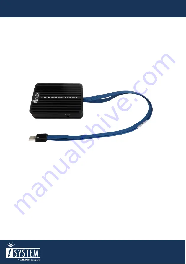
Page 4: ...T interface via USB C connector Its small and compact hardware size allows for connecting to a target microcontroller in a confined space as far as 10 m away The Active Probe supports up to 1 parallel...
Page 5: ...prietary FNet Debug signal valid input voltage range 5 0V max 5 5V Power consumption Max 1 5W dependent on operation mode Number of supported AGBT lanes 1 lane Maximum AGBT bitrate 5Gbps AGBT clock so...
Page 6: ...A5 B8 DAP1 DAP Data I I O Optional 2nd DAP data DAP2 A6 B7 nTRST Output O I O Optional 3rd DAP data DAP3 A7 B6 NC Not Connected O DAP Clock DAP0 A8 B5 Vref Reference Voltage I Not Connected NC A9 B4 N...
Page 7: ...o use Blinking green Establishing connection with the BlueBox Blinking blue Reprogramming SPLASH Permanently magenta Golden image loaded and ready to use D FNet connector that connects the Active Prob...
Page 8: ...controlled by the debugger For example the debugger can periodically service an external watchdog through the mDIO output or just read and record an external signal through the mDIO input It must be o...
Page 9: ...converter to the Active Probe Used physical USB C type connector doesn t feature the USB interface as someone could presume there is no way to incorrectly insert it but rather the Infineon AGBT Aurora...
Page 10: ...nd HSTCU USB C pinout Blue colored signals are trace signals The following pinout is valid on the target side Signal Direction Signal Description Signal Pin Pin Signal Signal Description Signal Direct...
Page 11: ...Signal Direction Signal Description Signal Pin Pin Signal Signal Description Signal Direction Ground GND A1 B12 NC Not Connected Not Connected NC A2 B11 NC Not Connected Not Connected NC A3 B10 NC Not...
Page 12: ...DAP clock O Ground GND 5 6 DAP2 Optional 2nd DAP Data pin I O Not Connected NC 7 8 DAP3 Optional 3rd DAP Data pin I O Ground GND 9 10 nRESET Reset I O 10 pin Infineon DAP pinout Signal Direction is d...
Page 13: ...evices are powered up This voltage difference is discharged over the BlueBox and the Target leading to the possible destruction of electronic components 4 Connect FNet cable of Active Probe to the Blu...
Page 14: ...5 0m FNet Cable BB FNET 500 mDIO Cable BB AP MDIO 20 The functionality can be extended through the use of various modules from IOM6 product line which enable capabilities from parallel debugging of mu...
Page 15: ...User Notes This page is intentionally left blank...
Page 16: ...www isystem com Visit our website for Support isystem com support Tutorials isystem com getting started Knowledge Base kb isystem com...