background image

TASCAM DR-701D 

11


8

Linear timecode (LTC)

When something is connected to the BNC 

connector, the internal timecode generator 

synchronizes with the linear timecode.
Operation will continue using the internal 

generator if the connection is interrupted.

Selecting the monitored signal

1.  When the Home Screen is open and the unit 

is stopped, paused, in recording standby or 

recording, press the MONITOR button to open 

the 

MONITOR SELECT

 screen.

2.  Turn the DATA dial to select which signal to 

monitor.

Option

Meaning

MIX

Monitor a mix in stereo.

CH1

Monitor the channel 1 input sound.

CH2

Monitor the channel 2 input sound.

CH3

Monitor the channel 3 input sound.

CH4

Monitor the channel 4 input sound.

CAMERA IN Monitor the   connector signal.
CH1-2

Monitor a mix of channels 1–2.

CH3-4

Monitor a mix of channels 3–4.

HDMI1*

Monitor the HDMI 1 input sound.

HDMI2*

Monitor the HDMI 2 input sound.

HDMI3*

Monitor the HDMI 3 input sound.

HDMI4*

Monitor the HDMI 4 input sound.

HDMI5*

Monitor the HDMI 5 input sound.

HDMI6*

Monitor the HDMI 6 input sound.

HDMI7*

Monitor the HDMI 7 input sound.

HDMI8*

Monitor the HDMI 8 input sound.

HDMI1-2*

Monitor a mix of HDMI 1-2.

HDMI3-4*

Monitor a mix of HDMI 3-4.

HDMI5-6*

Monitor a mix of HDMI 5-6.

HDMI7-8*

Monitor a mix of HDMI 7-8.

*The HDMI options will appear when synchro-

nized with HDMI.

NOTE

The monitoring options depend on the HDMI 

input and output settings.

3.  When finished selecting the monitoring signal, 

press the DATA dial or MONITOR button to 

return to the Home Screen.

NOTE

When 

CAMERA IN

 is selected, you can monitor 

the input sound through the 

PHONES

 jack, 

but the level meters will show the input sound 

according to the recording mode.

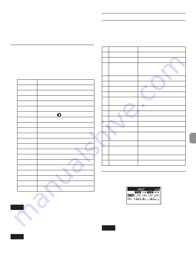
Menu structure

Press the MENU button the first time to open the 

INPUT

 menu page. In the future, pressing this button 

will reopen the menu page that was last open.
The menu screen has 18 pages organized by types of 

menu items.

Page name

Contents

1 INPUT

Make input settings.

2 MIXER

Make mixer settings.

3 PHASE/DELAY

Make settings for input phase 

and to compensate for mic 

distance.

4 LEVEL CONTROL Make input level settings.
5 TRIM GANG

Make gang settings.

6 OUTPUT LEVEL

Make output level settings.

7 MIC POWER

Make mic power settings.

8 RECORD

Make recording channel 

settings.

9 REC SETTING

Make recording settings

10 FILE

Make file settings.

11 MEDIA

Make media settings.

12 TIME CODE

Make timecode settings.

13 SLATE TONE

Make slate tone settings.

14 HDMI AUDIO 

ASSIGN

Make HDMI output audio 

assignments.

15 METER/TRIM

Make meter and trim settings.

16 POWER 

MANAGEMENT

Make power management 

settings.

17 REMOTE

Make remote control settings.

18 SYSTEM

Make system settings.

Basic operation procedures

1.  Press the MENU button to open the 

INPUT

 page.

2.  Turn the DATA dial to select (highlight) a menu 

page or an item to be set.

3.  Press the DATA dial to move the cursor to 

(highlight) the setting content.

NOTE

When a menu page showing 

CH1

CH2

CH3

 and 

CH4

 icons is open, press the 

DATA

 dial or a 

1/

8

2/

7

3/

/

 or 

4/

.

 button to select that 

channel.

4.  Turn the DATA dial to change the setting.
5.  Press the DATA dial or MENU button to set a 

different item.

Summary of Contents for DR-701D

Page 1: ...D01271700B ENGLISH FRAN AIS ESPA OL DEUTSCH ITALIANO OWNER S MANUAL MODE D EMPLOI MANUAL DEL USUARIO BEDIENUNGSANLEITUNG MANUALE DI ISTRUZIONI DR 701D Linear PCM Recorder for DSLR...

Page 2: ...Wiesbaden Erbenheim Germany TEAC SALES TRADING SHENZHEN CO LTD Phone 86 755 88311561 2 Room 817 Block A Hailrun Complex 6021 Shennan Blvd Futian District Shenzhen 518040 China TASCAM is a trademark of...

Page 3: ...tandards Declaration of Conformity Responsible party TEAC AMERICA INC Address 1834 Gage Road Montebello California U S A Telephone number 1 323 726 0303 This device complies with Part 15 of the FCC Ru...

Page 4: ...ation tape or something like that to prevent them from contacting other batteries or metallic objects When throwing used batteries away follow the disposal instructions indicated on the batteries and...

Page 5: ...h the crossed out wheeled dust bin symbol e The return and collection systems are available to the end users For more detailed information about disposal of waste batteries and or accumulators please...

Page 6: ...exposed directly to rain or other water Do not place this unit on top of a power amplifier or other device that generates heat If this unit is placed near a power amplifier or other device with a lar...

Page 7: ...d using plugs from external devices do not apply excessive force to the plugs Doing so could damage the equipment a HOLD switch s PHONES volume d PHONES jack 3 5mm stereo mini jack f EXT IN 1 2 connec...

Page 8: ...shows the recorder operation status Indicator Meaning 8 Stopped 9 Paused 7 Playing back Searching forward m Searching backward Skipping to the beginning of the next file Skipping to the beginning of...

Page 9: ...2 Preparation Powering the unit 8 8 Using AA batteries 1 Open the front cover on the front of the unit 2 Pull the lever on the battery compartment cover down to open it 3 Install 4 AA batteries with t...

Page 10: ...3 5mm stereo mini plug cable commercial ly available to connect the OUT jack on the right side of this unit with the external mic input on the camera 8 8 When you want to input audio from the camera...

Page 11: ...r MONITOR button to return to the Home Screen NOTE When CAMERA INis selected you can monitor the input sound through the PHONES jack but the level meters will show the input sound according to the rec...

Page 12: ...bs to adjust the input levels Guidelines are shown at 20dB and 12dB Set levels so that they average around 20 dB and have a maximum level of 12 dB Set the input levels so that the 1 4 knob PEAK indica...

Page 13: ...ording Channels 1 4 and a stereo mix will all be recorded as a single file Recording MONO STEREO POLY 6ch 8 8 Make recording settings 1 Select the FILE TYPEitem on the REC SETTINGpage See Basic operat...

Page 14: ...of the next file Connecting with a computer You can transfer audio files on the SD card in the unit to a computer as well as transfer audio files from the computer to the unit Connecting with a comput...

Page 15: ...ff frequency Set the input gain Home Screen w MENU w INPUTw GAIN Sets the input gain Adjust the input level manually 1 2 3 4 knobs Watch the meters and set the recording level so that they do not peak...

Page 16: ...voltage Restore the unit to its default settings Initialize Home Screen w MENU w SYSTEMw INITIALIZE Use this function to restore all settings to their factory defaults Format an SD card Format Home Sc...

Page 17: ...e Sys File The system file required to operate this unit is invalid When this message appears press the DATA dial to automat ically create a new system file Layer too Deep Folders can be created down...

Page 18: ...nit connected to a computer by a USB cable 8 8 The SD card is not recognized Confirm that the SD card is inserted completely 8 8 Playback is not possible If you are trying to play a WAV file confirm t...

Page 19: ...jack Audio performance 8 8 Frequency response 20 Hz 20 kHz 0 5 1 dB LINE IN to LINE OUT 44 1 48kHz sampling frequency JEITA 20 Hz 40 kHz 0 5 1 dB LINE IN to LINE OUT 96kHz sampling frequency JEITA 20...

Page 20: ...2 channels HDMI not connected Recording 2ch 48 kHz 16 bit WAV files About 2 30 Channels 1 2 used Channels 3 4 unused 3mA phantom power used for 2 channels HDMI input connected 1080 60i Recording 2ch 4...

Reviews: