background image

TASCAM  SERIES 102i / SERIES 208i

2 - Names and Functions of Parts
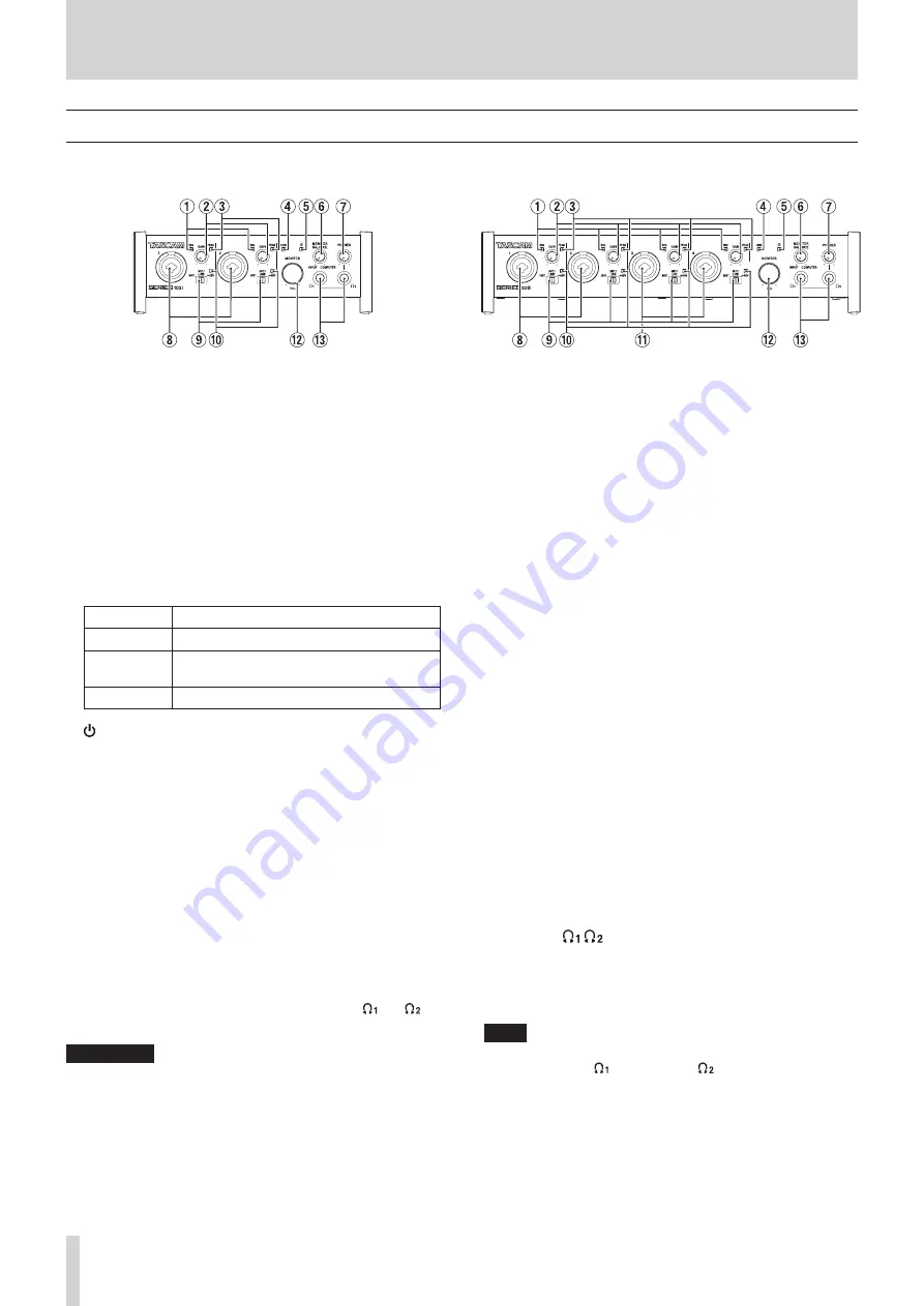
Front panel

SERIES 102i

SERIES 208i

SIG indicators

These light green when signals (of at least -32 dBFS) are 

input.

GAIN knobs

Use to adjust the input levels of the input jacks.

PEAK indicators

These light red when signals are about to distort (-1 dBFS or 

higher).
Adjust these so that the 

PEAK

 indicators do not light red.

USB indicator

This indicator shows the status of the unit by lighting, 

blinking and turning off.

Status

Meaning

Lit

Good USB connection

Blinking

Bad USB connection (disconnected or error 

occurred)

Unlit

Operating in standalone mode

 indicator

This indicator lights when the 

STANDBY

 (

u

) switch is set 

to ON.
This indicator blinks if the clock source or OPTICAL input is 

irregular (when the clock source is set to OPTICAL).

MONITOR BALANCE knob

Use this to adjust the balance between the signals from this 

unit’s input jacks and the output signals from the computer.
The volume of signals input through this unit's input jacks 

increase the more the 

MONITOR BALANCE

 knob is set 

to the left (

INPUT

) and signals output from the computer 

increase the more this is set to the right (

COMPUTER

).

This knob does not affect the recording level of input signals.
Input monitoring without lag is possible by monitoring the 

signals from the input jacks (direct monitoring).

PHONES knob

Use to adjust the output levels of the 

PHONES 

 and   

jacks.

V

CAUTION

Before connecting headphones, minimize the volume with 

the 

PHONES

 knob. Failure to do so could result in a sudden 

loud noise that could harm hearing, for example.

1-2 input jacks

These analog inputs are XLR/TRS combo jacks.
These support high impedance input, including direct guitar 

input.
Use the input switches (

9

) to select balanced line (MIC/LINE) 

or unbalanced (INST) input for the TRS jacks.
When directly connecting a guitar, bass or other instrument, 

set the input switch (

9

) to 

INST

.

Input switches

Set according to the input source of each input jack.

INST

: Select when connecting a guitar, bass or other high-

impedance instrument. This makes it an unbalanced 

input for high impedance.

MIC/LINE

: Select when connecting a balanced-output mic or 

line-level-output device.

+48V

:  This pr48V phantom power to the 

1-2

 XLR 

Jacks and 

3-4

 XLR jacks.

+48V indicators

These indicators light when their input switches (

9

) are set 

to 

+48V

.

3-4 input connectors (SERIES 208i only)

These analog inputs are XLR/TRS combo jacks.
These support high impedance input, including direct guitar 

input.
Use the input switches (

9

) to select balanced line (MIC/LINE) 

or unbalanced (INST) input for the TRS jacks.
When directly connecting a guitar, bass or other instrument, 

set the input switch (

9

) to 

INST

.

MONITOR knob

Use to adjust the output level of the 

LINE OUT 

(BALANCED) 1-2

 (

p

) jacks on the back of the unit.

PHONES  /  jacks

Use this standard stereo jack to connect stereo headphones.
These output the same signals as the 

LINE OUT 

(BALANCED) 1-2

 jacks (

p

) on the back of the unit.

Use an adapter to connect headphones with a mini plug.

NOTE

The same signals are output at the same level (volume) from 

both 

PHONES

   and 

PHONES

   jacks.

Summary of Contents for 208i Series

Page 1: ...D01355520A SERIES 102i SERIES 208i AUDIO INTERFACE REFERENCE MANUAL Before connecting this unit to a computer you must download and install dedicated software on the computer...

Page 2: ...LINK button overview 19 INFORMATION page 20 ROUTING page 21 Monitor Control screen SERIES 208i only 22 Using the Settings Panel View menu 22 Initializing the Settings Panel 23 Resetting the reverb se...

Page 3: ...One and GarageBand o o AC adapter PS P1220E included with 3 alternate plugs o o DAW software and plug in effects included Note about computer operation If you are unsure about anything related to the...

Page 4: ...ize the volume with the PHONES knob Failure to do so could result in a sudden loud noise that could harm hearing for example 81 2 input jacks These analog inputs are XLR TRS combo jacks These support...

Page 5: ...u Tip HOT Ring COLD Sleeve GND pLINE OUT BALANCED 1 2 jacks These standard TRS jacks are analog line outputs The nominal output level is 4 dBu Tip HOT Ring COLD Sleeve GND aMIDI OUT connector This 5 p...

Page 6: ...guarantee operation with all computers that meet the above requirements Even computers that meet the same system requirements might have processing capabilities that differ according to their setting...

Page 7: ...2 Uncompress the saved software zip file on the computer desktop or another location 3 Double click the TASCAM_SERIES_102i_208i_Installer_x xx exe x xx is the version number file in the folder that a...

Page 8: ...ress the zip file first and then double click the disk image file 3 When the installer starts click the Continue button 4 Next select the desired language and click the Continue button 5 Click the Rea...

Page 9: ...tting The Gatekeeper setting can be changed using the Allow applications downloaded from item on the General page of the Security Privacy pane of the System Preferences To change this you must click t...

Page 10: ...plug NOTE When purchased new the included PS P1220E AC adapter for the unit has an outlet plug A already attached There should be no need to change the plug 1 Move the knob 1 on the PS P1220E AC adap...

Page 11: ...cable included with this unit to connect an iOS device NOTE i i When connected this unit will not provide power to the iOS device i i iOS does not support 176 4 192 kHz sampling frequencies Audio con...

Page 12: ...phono input jacks must be connected between them Connecting monitor speakers Connect monitor speakers powered speakers or an amplifier and speaker system to the LINE OUT MONITOR 1 2 jacks on the back...

Page 13: ...e SERIES 208i ATTENTION When you open the Settings Panel the state will be the same as the last time closed However the setting values on each page MIXER INFORMATION and ROUTING will be the same as wh...

Page 14: ...will appear dimmed 5Output adjustment section Make REVERB AUX MASTER and STEREO MASTER settings here see Output adjustment section on page 18 This can be selected when set to BROADCAST but it will alw...

Page 15: ...and the sound returns to its uncompressed level after the input sound goes below the threshold level Range 10 ms 1000 ms default 10 ms NOTE i i If the input is a stereo signal stereo linked channel o...

Page 16: ...elected button lights Status Meaning PRE button unlit POST button unlit default The signal is not sent to the AUX bus PRE button lit The signal is sent to the AUX bus before adjustment by the channel...

Page 17: ...level display area e NOTE Shift click the fader to set it to 0 dB wChannel level meter These meter show the signal levels of each channel The channel level meter appear green at levels of 12 dB or le...

Page 18: ...0 dB to 6 dB 4AUX MASTER 2 4 knobs and indicators Use these to adjust the send master levels of the signals sent to the AUX 2 4 buses Range inf to 6 dB default 0 dB Drag the 2 4 knobs up or down to ad...

Page 19: ...areas The setting of the odd channel is shown NOTE When a LINK button is on lit the select button names change to a name used when the stereo link is active Examples When the INPUT 1 and INPUT 2 butt...

Page 20: ...OPTICAL IN S MUX connector is used If the connected device is a TASCAM device and 3 Rate setting is Auto TASCAM Device the input clock signal will be automatically identified and set OPTICAL B SERIES...

Page 21: ...AUX 4 COMPUTER 1 Output signals from Computer BUS 1 4 COMPUTER 2 COMPUTER 3 COMPUTER 4 SERIES 208i options Option Meaning INPUT 1 Output signals as Analog Digital Input 1 4 INPUT 2 INPUT 3 INPUT 4 OP...

Page 22: ...ames selected in the monitor output selection area 3 are shown Range inf to 0 0 dB default 0 0 dB 3Monitor output selection Use these to select the output channels The names of the selected output cha...

Page 23: ...all channels center C i i Channel faders all channels 0 0 dB i i LINK buttons all channel pairs off i i REVERB buttons on i i REVER RETURN knob inf i i AUX MASTER 1 REVERB knob 0 dB i i AUX MASTER 2 4...

Page 24: ...he unit you can use them to operate the unit in standalone mode when it is not connected to a computer by USB See Saving Settings Panel settings to the unit on page 26 for details NOTE The Buffer Size...

Page 25: ...Load in the submenu to change the Settings Panel settings to the settings in the selected scene memory Windows version Mac version ATTENTION A scene memory that has never been saved contains no Settin...

Page 26: ...reset all the scene memories NOTE Click the Cancel button to return to the previous screen without resetting the 10 scene memories Saving Settings Panel settings to the unit You can transfer the curr...

Page 27: ...or the firmware is released a notification about automatic updating will appear when the software is launched Software update notification Firmware update notification Click the Update now button to...

Page 28: ...Windows Media Player is running the software will not recognize that the device has been changed In this case restart Windows Media Player i i If you still cannot hear sound after correctly making the...

Page 29: ...recording for example Settings in standalone mode When operating in standalone mode input signals pass through the built in digital mixer and output selector which are set at fixed values and are out...

Page 30: ...e number Range Thru Velocity Note on Thru Note off Aftertouch Polyphonic Thru Channel Pitch bend Thru Control change Thru Program change Thru Setting range System exclusive Thru System common Position...

Page 31: ...problem connect the unit to a different USB port on the computer There is no sound even when playing back on the computer Confirm that the MONITOR BALANCE knob on the unit is not turned all the way to...

Page 32: ...ce NOTE If an item is not shown select the Show Additional Plans downward triangular button Alternatively click Create a power plan Using Mac 1 Open System Preferences from the Apple menu and select E...

Page 33: ...Analog outputs Monitor outputs balanced LINE OUT 1 2 Connectors 6 3mm 1 4 standard TRS jacks Tip HOT Ring COLD Sleeve GND Output impedance 230 Nominal output level 4 dBu 1 228 Vrms Maximum output lev...

Page 34: ...g systems Windows Supported operating systems Windows 10 32 bit Windows 10 64 bit Windows 8 1 32 bit Windows 8 1 64 bit Windows 7 32 bit SP1 or later Windows 7 64 bit SP1 or later Windows Vista and Wi...

Page 35: ...DC12V AC adapter PS P1220E Power consumption SERIES 102i 7 2 W SERIES 208i 14 W Dimensions SERIES 102i 186 65 160 mm width height depth SERIES 208i 296 65 160 mm width height depth Weight SERIES 102i...

Page 36: ...nsional drawings SERIES 102i 186mm 65mm 160mm SERIES 208i 296mm 65mm 160mm o o Illustrations in this manual might differ in part from the actual product o o Specifications and external appearance migh...

Page 37: ...R AUX1 BUS AUX2 BUS AUX3 BUS AUX4 BUS Computer 1 Computer 2 Computer 3 Computer 4 Computer 5 Computer 6 Computer 7 Computer 8 IN 1 SOLO MONITOR BALANCE RETURN DAC DAC DAC ON OFF MIC LINE INST IN 1 MIC...

Page 38: ...tps www tascam eu Phone 44 1923 797205 Meridien House Ground Floor 69 71 Clarendon Road Watford Hertfordshire WD17 1DS United Kingdom TEAC EUROPE GmbH https www tascam de Phone 49 611 71580 Bahnstrass...

Reviews: