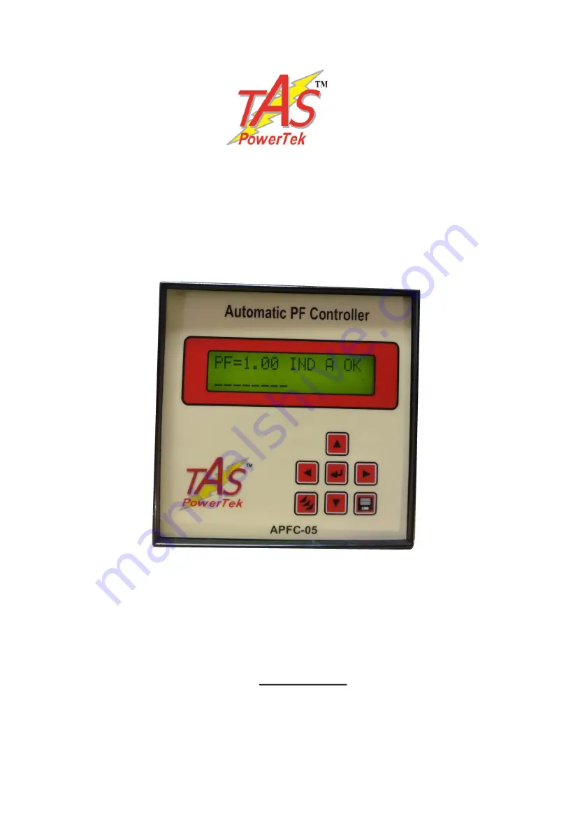
Automatic Power Factor Controller
APFC-05
User Manual
Version 1.0
TAS POWERTEK PVT.LTD
.
VERSION 1.0 Updated on: FEB. 18, 2015
Page 1: ...Automatic Power Factor Controller APFC 05 User Manual Version 1 0 TAS POWERTEK PVT LTD VERSION 1 0 Updated on FEB 18 2015...
Page 2: ...transmission or use of this document or its contents is not permitted without express written authority Offenders will be liable for damages All rights are reserved Because of continuous improvements...
Page 3: ...Screen Details 12 13 Keyboard details 14 Display of various parameters 15 Sub menu for display of parameters 16 Method of Keyboard Display usage 17 to 19 Keyboard Display operations 20 21 Edit Paramet...
Page 4: ...iz Binary Un equal user defined C Series preset series E Series user defined Output banks control for either 4 6 or 8 Capacitor Banks Standard 96x96 mm Plastic Cabinet for panel door flush mounting Pr...
Page 5: ...FC 05 6 or 8 APFC 05 8 Isolated NO contacts of rating Inductive Load 0 5A 250Vac Operating Temperature 0 to 55oC Storage temperature 0 to 70oC Relative Humidity 10 to 95 Non Condensing AC Mains Supply...
Page 6: ...Front fascia Keyboard LCD display LCD Display Key pad PF 0 98 IND A OK LCD Display Contrast Adjustment Slot for small Allen Key at the Top Surface TAS POWERTEK PVT LTD VERSION 1 0 Updated on FEB 18 20...
Page 7: ...BACK SIDE TERMINALS Auxiliary Measurement Voltage Load Current CT Output Terminals 5 TAS POWERTEK PVT LTD VERSION 1 0 Updated on FEB 18 2015...
Page 8: ...nductive smallest Capacitor bank kVAr x 2 width 6 kVAr Ind kVAr Cap PFLOWER PFUPPER kW PFLOWER PFUPPER smallest Capacitor bank kVAr x 2 width Case 2 PF UPPER as Capacitive PF LOWER set as Inductive kW...
Page 9: ...ber of switching operations during higher loading conditions This ensures better life expectancies of the switched capacitors as well as the switching devices This methodology of kVAr compensation red...
Page 10: ...er diagram shown above The voltage feedback is taken from the LT bus system itself This type of scheme is used when user is interested in maintaining the healthy Power factor on secondary side of the...
Page 11: ...he load sensing CT is put at the input of the transformer on HT side This scheme is preferred with LT consumers of electricity where the metering is carried out on HT side This scheme gives the compen...
Page 12: ...diagram Either of the above specified schemes can be selected by the user based on the system requirement L O A D L3 N S1 S2 Load Current L1 N APFC 05 P1 P2 L2 L1 TAS POWERTEK PVT LTD VERSION 1 0 Upda...
Page 13: ...with S common Output commands to capacitor contactors APFC 05 COM common C1 C8 potential free relays maximum of up to 8 Stages 0 5A 230Vac Inductive Load F2 Fast Blow Fuse Protected Rear side terminal...
Page 14: ...IND A OK bank is in ON state bank is in OFF state bank is declared as FIXED is in ON state bank is declared FAULTY not available for use output stage is not used in the system bank is in DISCHARGE mo...
Page 15: ...M defines Manual mode Total number of banks that are operational are eight Bank no 1 is declared as fixed and is in ON condition Bank nos 2 and 3 are in ON condition Bank no 4 is declared as faulty Ba...
Page 16: ...ers Also use to change status of bank RIGHT key Used to shift the cursor to right also used to increase the contrast of LCD in default display screen mode LEFT key Used to shift the cursor to left als...
Page 17: ...p to 15th Displays the measured kVAr value of each connected output step Displays the internal cabined temperature Displays the version of software 15 Values of various parameters can be viewed by usi...
Page 18: ...16 continued Sub menu for display of parameters TAS POWERTEK PVT LTD VERSION 1 0 Updated on FEB 18 2015...
Page 19: ...rent modes Enter the 4 digit Password by using keys PRESS Enable If Password Option is Enable Disable Disable IF PASSWORD Correct NO YES Continued on next page PRESS Enter Password Default Display mod...
Page 20: ...5 6 7 8 9 10 11 12 13 14 15 16 18 Continued on next page Select 1 Edit Parameter Select 2 Auto Operation Select 3 Manual Operation Default Display mode TAS POWERTEK PVT LTD VERSION 1 0 Updated on FEB...
Page 21: ...F 0 87 IND M OK Edit Parameters General and IO Edit Parameters System Edit Parameters Fault Edit Parameters Step Edit Parameters Utilization Cntr General parameters Grid transformer APFC system relate...
Page 22: ...em ON OFF Declaring specific bank s faulty Masking of the banks so that once auto mode is selected these faulty declared banks would not be used for PF correction For Declaring banks faulty or Resetti...
Page 23: ...r system settings Fault Fault settings Step Capacitor bank step settings Utilization counter Bank operations utilization counters After selecting the type press ENTER to enter the sub menu of that spe...
Page 24: ...rsing the CT Polarity in case the kW reading is a Ve value 22 Password Enable or disable password Value 0 Disable 1 Enable Change Password Set new value of password 4 digit Factory default password is...
Page 25: ...der Voltage For Under Voltage conditions Over Load If APFC 05 detects the supply system is overloaded then it is sometimes recommended to remove the capacitors out of circuit to reduce the fault curre...
Page 26: ...Smallest bank kVAr tan cos 1 PFLOWER tan cos 1 PFUPPER Under Load kW value setting 1 25 x Smallest bank kVAr tan cos 1 PFUPPER tan cos 1 PFLOWER For PFUPPER Capacitive and PFLOWER Capacitive 24 Under...
Page 27: ...lower limit is for normal operation resume Step Health Check APFC 05 carries out on line monitoring of the kVAr values of every step This is when the step is put in the tolerance limit defined here is...
Page 28: ...of overcompensation cannot be turned OFF The banks can only be turned OFF under fault conditions if settings in fault are defined Correction Type APFC 05 can have bank configurations that are defined...
Page 29: ...s explained earlier this series is the user defined series Digits can be adjusted from 1 to F i e 1 to 15 C E Bin Series Bank kVAr The kVAr defined here is the capacitor bank KVAR of the smallest bank...
Page 30: ...unter Bank n Options are Yes and No Declaring specific bank number with Yes and pressing save command will reset the specific bank utilization counter to zero This is normally done in case the specifi...
Page 31: ...ars and or Lugs by rubbing it with Polish Paper to remove the oxidation layer Provide contact paste in between the contacts surfaces Not performing this can result in to a weaker source point for Capa...
Page 32: ...the panel and replace all the fuses or turn on MCBs MCCBs if they are provided instead of fuses Turn on the panel 5 Put APFC 05 back in Manual mode and turn ON OFF the individual steps Use Tong tester...
Page 33: ...nnections from RLY to contactors Some Capacitor banks are declared as faulty even if they are checked to be OK Individual step health monitoring is enabled and tolerance limits set are too stringent C...
Page 34: ...ary supply R C Snubbers or MOVs for AC Circuits or free wheeling diodes for DC Circuits are not put with contactor coils Use the different phase for control supply of contactors and for APFC 05 supply...
Page 35: ...Land Line Phones 0091 253 6694956 Sales Marketing 0091 253 6694955 Customer Support Service Fax 0091 253 6694 955 Working Hours 9 30 AM to 6 30 PM Weekly Off Saturdays E mail sales taspowertek com We...