Taisync ViuRC5 User Manual
www.taisync.com
Page 1: ...Taisync ViuRC5 User Manual www taisync com...
Page 2: ...aces 5 2 5 Status Indicators 6 3 Connections 8 4 Before Use 10 4 1 Remote Controller Operation 10 4 2 Antenna Installation 11 5 Device Management 13 5 1 RC Settings 13 5 1 1 Stick calibration 13 5 1 2...
Page 3: ...ackage Contents Remote Controller Air Unit Accessories No Item Quantity 1 Charger 1 2 USB cable 1 3 Air unit adaption cable 2 4 Air unit antenna 2 5 Ethernet cable 1 6 Power cable 1 7 Air unit IP came...
Page 4: ...4 Operational temperature 10 55 Air unit Dimension 83 50 22 5mm Weight 41g Voltage input 6S 16S 22 2V 59 2V Power consumption 8W Interface ETH 2 TTL 2 S BUS 1 Remote controller Display 5 5 LCD touch p...
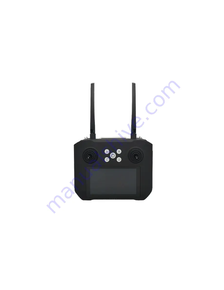
Page 5: ...3 2 2 RC Controls Touchscreen Stick Dial Switch Stick Switch Dial Antenna Battery Indicator Power Button Button Button...
Page 6: ...Left upper 3 point switch 6 T2 Left lower 3 point switch 7 T3 Right upper 3 point switch 8 T4 Right lower 3 point switch 9 W1 Left dial 10 W2 Left dial 11 A Button A Self locking by default 12 B Butt...
Page 7: ...5 2 3 Remote Controller Interfaces 2 4 Air Unit Interfaces SIM Debug Power TF...
Page 8: ...2 5 1 RC status light indicators 1 Power indicator It will be solid on in red after RC is powered on 2 Battery level indicator Battery level indication 0 25 25 50 50 75 75 100 On Off Power indicator...
Page 9: ...the box If user would like to do bind for particular case please follow below steps 1 Power on air unit power on remote controller antennas must be installed before power on 2 Press and hold the bind...
Page 10: ...8 3 Connections Here take the Pixhawk 4 as an example XT60 connector voltage input 6S 16S FC Antennas...
Page 11: ...controller but make sure baud rate of flight controller is 115200 and the used telemetry port of air unit is TTL1 2 Video connection Video connection settings have been made already in pre installed...
Page 12: ...re Use 4 1 Remote Controller Operation 4 1 1 RC power on off 1 Power on Press the power button to start the power system then press and hold the power button till it beeps Power button Battery level i...
Page 13: ...get the screen into sleep when the remote controller is powered on and invoke by it also 4 1 2 RC charging Please use the factory delivered power adapter and cable to charge the remote controller 1 Co...
Page 14: ...h each other antenna RF cable and SMA connector should not be directly contacted to metal carbon fiber parts 2 RF cables should keep distance from devices like electric motor or electric tilt which ma...
Page 15: ...1 1 Stick calibration Stick correction can be performed periodically to ensure the accuracy of stick channel outputs Stick calibration method 1 Before start please make sure both sticks stand still wi...
Page 16: ...eady but the blue dots are not at the central it means the stick neutral position has an offset Now do not move the stick touch on Next to do neutral position calibration 4 Go on with end point calibr...
Page 17: ...int operation direction reversal and channel mapping can be set by user via channel settings Servo travel end point Default servo travel end point ranges 200 1800 User can also change the end point ma...
Page 18: ...s normal R means reverse Channel mapping ViuRC5 has 14 channels in total and allow user to define the mapping relations between logical communication channel and physical channel button switch stick e...
Page 19: ...e output accuracy of volume channel Neutral position and end point can be calibrated Volume calibration method 1 Before start please make sure both sticks stand still without position offset caused by...
Page 20: ...the volume neutral position has an offset Now do not move the volume touch on Next to do neutral position calibration 4 Go on with end point calibration According to the prompt move volume fully in e...
Page 21: ...ton setting There are options of self locking and non self locking for the buttons of A B C and D Self locking for button A and button B non self locking for button C and button D by default user can...
Page 22: ...nnel will be 1800 as soon as user release the button the output goes back to 200 Stick setting There are options of American Japanese Chinese and custom for stick mode 5 2 Transceiver There is radio t...
Page 23: ...ency to use Note 1 Baud rate of serial telemetry is hard coded as 115200 in pre installed QGC so baud rate of the radio link should keep aligned if pre installed QGC is used 2 All the parameters only...
Page 24: ...TP server is used for air unit remote firmware upgrade IP address of air unit 192 168 199 18 is set here as the TFTP server IP address If air unit IP address is changed the server IP address must be m...
Page 25: ...heck for firmware updates of remote controller transceiver and app tool Touch on Run to do the firmware version check results will be listed If it s not the latest upgrade can be done online over the...
Page 26: ...level is enough for the whole flight before take off 2 Make sure antennas are properly installed to avoid drone body blockage and do not power on device without antenna installation 3 Check the firmw...
Page 27: ...ower on air unit and remote controller press and hold the physical bind button of air unit and touch on the software binding button of RC tool of controller 4 How to switch the camera video and how to...