


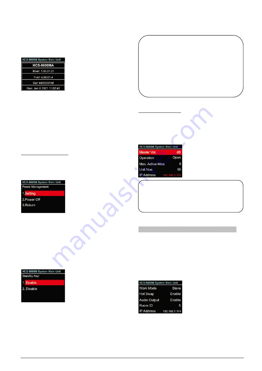
16. About
CMU information
includes: firmware version,
corporation information and series number, shown as
in the following figure - press function knob to return to
upper level menu.
17. Return
Select this item and press the function knob to return to
the LCD initial interface. The screen also returned to
LCD initial interface automatically if no operation on
menu in 2 minutes.
D) Power Management
Press and hold the “STANDBY” button to enter power
management interface, as shown as the following
figure:
a). Rotate function knob to select “Setting”, “Power
Off” or “Return”;
If “
Power Off
” is selected, the main unit switches
to standby mode;
If “
Return
” is selected, the main unit exit power
management interface;
If “
Setting
” is selected, then select enable the
“STANDBY” button or not;
b). Rotate function knob to select “Enable” or
“Disable”;
If “
Enable
” is selected, power on through the
“POWER” switch and the “STANDBY” button;
If “
Disable
” is selected, power on directly
through the “POWER” switch;
c). Press function knob to save and return to the upper
level menu.
E) Connecting to PC
When connecting CMU to the Conference
management system software or webserver, the IP
address changes to red, as shown as the following
figure:
2.1.4 Configuration and operation - slave mode
When dual main unit hot spare or conference room
combination occurs, the spare main unit or the main
unit in the slave conference room works in slave mode.
The LCD display shows as in the following figure in
salve mode, press function knob to enter the menu
settings.
The menu includes:
1. Work Mode:
same as this menu operation in the
main mode;
2. Hot Swap:
same as this menu operation in the
main mode;
Note:
When power down the main unit, please press
and hold the “STANDBY” button to enter power
management interface, then select
“Power Off
”
and press function knob to confirm. Please do
not use the switch button on the back of the main
unit to shutdown directly; otherwise, it may lead
to startup error.
Note:
Conference management system software
and webserver can not be connected to the
same main unit at the same time.
27
Summary of Contents for HCS-8600 Series
Page 1: ...Paperless Multimedia Congress System Installation and Operating Manual V 1 0...
Page 14: ...Figure 1 1 4 HCS 8668 Series Paperless Multimedia Congress System connection diagram 3...
Page 91: ...3 3 2 Fixed installation Figure 3 3 2 Fixed installation of HCS 8665 series congress unit 80...
Page 109: ...4 1 Functions and indications Front Side Bottom Figure 4 1 HCS 8685 Interpreter unit 98...
Page 118: ...Blue 107...
Page 145: ...Figure 6 2 3 HCS 8668 Series Paperless Multimedia Congress System connection diagram POE 134...
Page 180: ...Appendices Custom made cables Appendix Ethernet Cable 169...
Page 181: ...Appendix CBL4PK 01 Power Adapter Cable 170...
Page 182: ...Appendix CBL4PT 02 Power Branch Cable 171...


