


7-26
Coral IPx 800 Installation Manual
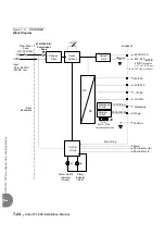
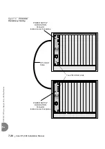
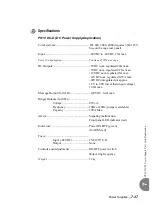
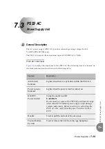
PS
19 D
C
-D
Po
wer Supp
ly Un
it wi
th D
upl
icati
on
7
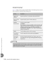
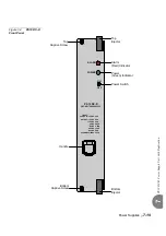
The PS19 DC-D is installed in the extreme left slot of the peripheral card cage.
The system may be configured for power redundancy with two PS19 DC-D units (one
in each cage) supporting two adjacent cages.
The Hot Standby system is designed to allow hot insertion and hot swaps of a
PS19 DC-D unit, such that, if one of the PS19 DC-D units malfunctions, system
operation is not interrupted because the second unit alone can continue powering
either cage.
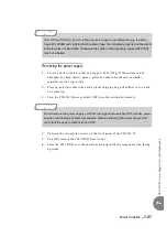
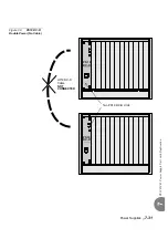
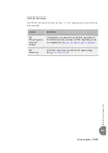
Installing the PS19 DC-D
1.
Verify that the PS19 DC-D power switch is turned OFF.
2.
Position the two guide ridges (located on the right panel of the power supply, at
top and bottom) into the card edge guides corresponding to the POWER SUPPLY
label on the bottom of the cage slot.
3.
Slide the PS19 DC-D power supply gently but firmly, until fully inserted into the
card cage. A slight resistance should be felt as the multi-pin connectors engage at
the rear of the power supply and backplane.
Do not force the unit into the slot. Irreparable damage may occur if the multi-pin
connectors mis-align while attempting to insert the unit. If more than slight
resistance is encountered, partially slide the unit out of the card cage and verify
the alignment of the guide ridges with the unit edge guides. If alignment appears
to be correct, remove the unit from the slot and inspect the multi-pin connectors
for bent pins and debris in the pin holes.
4.
Secure the power supply to the card cage by fastening the two captive screws,
located at the top and bottom of the unit to the cage.
5.
Turn the power switch ON, and verify that the green Power indicator is lit while
the red Alarm indicator is not lit.
4
Installation
Do not insert or remove the power supply unit from the cage when turned ON. Sudden
power surges could damage system components.
Summary of Contents for Coral IPx 500X
Page 2: ......
Page 4: ......
Page 10: ...vi...
Page 16: ......
Page 22: ......
Page 28: ......
Page 32: ...1 4 Coral IPx 800 Installation Manual Document Description 1 NOTES...
Page 34: ...1 6 Coral IPx 800 Installation Manual Special Symbols Used in this Document 1 NOTES...
Page 40: ......
Page 48: ...2 8 Coral IPx 800 Installation Manual Site Inspection 2 NOTES...
Page 90: ......
Page 116: ...3 26 Coral IPx 800 Installation Manual Shared Service and Peripheral Card Test 3 NOTES...
Page 118: ...3 28 Coral IPx 800 Installation Manual Installation Wrap up 3 NOTES...
Page 120: ......
Page 126: ......
Page 142: ...5 16 Coral IPx 800 Installation Manual Protection Devices 5 NOTES...
Page 150: ...5 24 Coral IPx 800 Installation Manual Terminal Data Communication Ports RS 232E 5 NOTES...
Page 242: ......
Page 278: ...6 38 Coral IPx 800 Installation Manual Cage Description and Installation 6 NOTES...
Page 292: ...6 52 Coral IPx 800 Installation Manual Coral IPx 800X Expansion Cage Description 6 NOTES...
Page 312: ...6 72 Coral IPx 800 Installation Manual System Configuration Options Coral IPx 800 6 NOTES...
Page 314: ......
Page 352: ...7 38 Coral IPx 800 Installation Manual PS19 DC D Power Supply Unit with Duplication 7 NOTES...
Page 368: ......
Page 372: ...8 4 Coral IPx 800 Installation Manual Common Control Cards 8 NOTES...
Page 382: ...8 14 Coral IPx 800 Installation Manual Software Authorization Unit SAU 8 NOTES...
Page 384: ...8 16 Coral IPx 800 Installation Manual MAP 8 NOTES...
Page 386: ...8 18 Coral IPx 800 Installation Manual LIU 8 NOTES...
Page 392: ......
Page 396: ...8 26 Coral IPx 800 Installation Manual HDC Card High Density Control 8 NOTES...
Page 399: ......


