background image

Function Description |

15

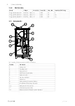
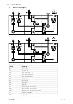
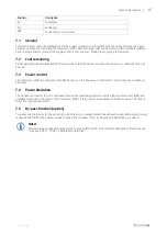
Position

Description

EV

Evaporator

CO

Condenser

HPS

Condenser pressure sensor

7.1

General

Control unit (UC) senses the temperature via the extract temperature sensor (ETS) and then keep the set extract tem-
perature by sequence controlling the compressor (CPR), heat exchanger (HE) and hot water- /electrical heater (HWL/H,
ELH). The temperature sensor in the supply air (SS) is min. and max. limiting the supply air temperature.

7.2

Cool recovering

Exchanger (HE) will automatically start to recover the cold in the extract air when the extract air is colder then the out-
door air.

7.3

Power control

The compressor (CPR) are step-less controlled between, in the frequency converter (FC), set minimum and maximum
frequency.

7.4

Power limitation

The frequency converter (FC) is continuously sensing the condensing pressure via the high pressure sensor (HPS) and
gradually slows down the speed of the compressor (CPR), if the pressure exceeds the set limitation value. This is done
to avoid a high pressure alarm.

7.5

By-pass function (option)

To reduce the energy use for the extract fan when there is no cooling demand the exhaust by-pass damper (accessory)
is opened and thereby the exhaust air does not pass the condenser (CO). At stopped unit all dampers are closed.

Note:

This instruction contains functions for the Topvex SoftCooler TR, for a complete description of functions see
"Topvex SR 09,11, TR 09-15 Installation instruction"

208767 | A006

Summary of Contents for Topvex TR 09 Series

Page 1: ...Document in original language 208767 A006 Topvex SoftCooler TR09 15 Access control system Installation instructions GB...

Page 2: ...208767 A006...

Page 3: ...ing the unit 7 6 4 Dividing the Topvex TR air handling unit 9 6 5 Duct connections 11 6 6 Condensation and Heat Insulation 11 6 7 Condensation drain 12 6 8 Electrical connection 12 7 Function Descript...

Page 4: ......

Page 5: ...er or lower limbs EN 60204 1 Safety of machinery Electrical equipment of machines Part 1 General requirements EN 60335 1 Household and similar electrical appliances Safety Part 1 General requirements...

Page 6: ...ape well Duct connections duct ends should be covered during storage and installation Do not connect tumble dryers to the ventilation system 3 Refrigerant Control Reporting Topvex SoftCooler TR comes...

Page 7: ...ig 1 Dimensions mm TR09 TR15 Drawn as left hand unit Model AA B C D E F G I J K L TR09 2630 1630 1120 810 895 104 129 129 105 210 700 TR12 2770 1740 1230 930 965 76 104 104 105 215 800 TR15 2820 1980...

Page 8: ...9230 20 5 5 4 3 Components Fig 2 Connections and basic components in left hand connected units Position Description 1 Compressor 2 Condenser coil 3 Evaporator coil 4 Filter drier with sight glass 5 E...

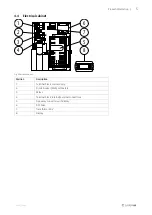
Page 9: ...7 8 Fig 3 Electrical cabinet Position Description 1 Terminal block mains supply 2 Circuit breaker MCB oil heaters 3 Relays 4 Terminal block internal external connections 5 Frequency converter with dis...

Page 10: ...here how to install Topvex SoftCooler are meant for indoor installation Place the unit on a horizontal flat surface It s important that the unit is completely levelled before it is put into operation...

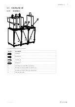
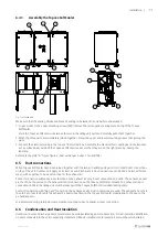
Page 11: ...Installation without by pass left hand unit Position Description Supply air Exhaust air Outdoor air Extract air 1 VAV Pressure transmitters accessory 2 Damper and motor outdoor air accessory 3 Damper...

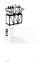
Page 12: ...tion Description Supply air Exhaust air Outdoor air Extract air 1 Exhaust air By pass 2 VAV Pressure transmitters accessory 3 Damper and motor outdoor air accessory 4 Damper and motor exhaust air acce...

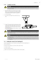
Page 13: ...it casing directly to the elec trical connection box See enclosed wiring diagram and chapter 6 8 1 table 2 for more information Warning The units electrical connection to the mains power supply must b...

Page 14: ...10 Installation A Fig 6 Illustration shows the left handed version of the unit 208767 A006...

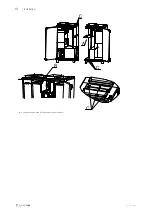
Page 15: ...ct connections on top of the unit Outdoor air Supply air Extract air and 2 Exhaust air Duct connections can be done on two different ways with or without a by pass function for the exhaust air For duc...

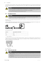
Page 16: ...SoftCooler Use the included plastic connection pipe which is to be cut to the correct height H according to the below figure See the below table for the relation of hight H and maximum under pressure...

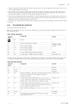
Page 17: ...al block Description Remark PE Ground 400V 3N 50Hz supplied via safety switch N N Earthed neutral supply voltage L1 L1 Phase supply voltage L2 L2 Phase supply voltage L3 L3 Phase supply voltage 28 G B...

Page 18: ...Fig 11 With by pass left hand unit Position Description EF Extract air fan SF Supply air fan SS Temp sensor supply air OS Temp sensor outdoor air ETS Temp sensor extract air UC Control unit RC Rotor...

Page 19: ...ssor CPR are step less controlled between in the frequency converter FC set minimum and maximum frequency 7 4 Power limitation The frequency converter FC is continuously sensing the condensing pressur...

Page 20: ...chapter 6 8 1 External Internal connections Internal operating cable connected see chapter 6 8 1 External Internal connections The two transparent pressure measuring tubes to the extract fan connected...

Page 21: ...ply and extract fan via the Topvex air handling units safety switch Turn on the mains supply for the Topvex SoftCooler via the working switch make sure that the voltage is on the display in the freque...

Page 22: ...the Topvex SoftCooler be closed for at least 5 minutes before reading Output frequency Param d001 Output current Param d002 Condenser pressure Param d004 Output frequency __________________Hz Output c...

Page 23: ...208767 A006...
Page 24: ...ler TR09 15Access control system Installation instructions 208767 en_GB 2020 01 27 A006 Systemair Sverige AB Industriv gen 3 SE 739 30 Skinnskatteberg Sweden Phone 46 222 440 00 Fax 46 222 440 99 www...

Reviews: