9
6.3.2
Installation procedure
Warning
Beware of sharp edges during mounting and maintenance. Make sure that a proper lifting device is used.
Use protective clothing.
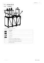
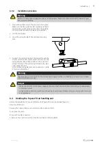
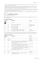
1 Prepare the surface where the unit is to be mounted.
Make sure that the surface is flat, levelled and that it
supports the weight of the unit. Perform the installa-
tion in accordance with local rules and regulations.
2 Lift the unit in place.
3 Level the unit with help of the enclosed mounting
feet
4 Connect the unit electrically to the mains through the
all pole circuit breaker, safety switch (accessory). The
wiring between the safety switch and the unit is led
through the top of the unit casing directly to the elec-
trical connection box.
See enclosed wiring diagram, and chapter 6.8.1, table
2 for more information.
Warning
The units electrical connection to the mains power supply must be preceded by an all pole circuit breaker
with a minimum 3 mm gap.
Danger
• Make sure that the mains power supply to the unit is disconnected before performing any maintenance
or electrical work!
• All electrical connections must be carried out by an authorized installer and in accordance with local rules
and regulations.
6.4
Dividing the Topvex TR air handling unit
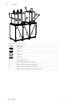
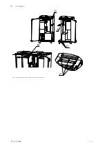
Before the installation of Topvex SoftCooler the Topvex TR has to be divided (figure 6).
How to split the unit:
Remove the heat exchanger, extract fan and the extract air filter
A. Remove the plate
B. Loose the cable connectors
C. Remove the 7 M10 screws that join the two halves of the appliance
208767 | A006
Summary of Contents for Topvex TR 09 Series
Page 2: ...208767 A006...
Page 4: ......
Page 14: ...10 Installation A Fig 6 Illustration shows the left handed version of the unit 208767 A006...
Page 23: ...208767 A006...

