

Section II
General Product Information
006-0006205
UPS-1500 Series
Rev ZC
13 of 60
05/28/2019
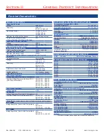
Electrical Characteristics
INPUT CHARACTERISTICS
Operating AC Input
Voltage
80-265 Vrms*
Frequency
47-65 Hz
(47-800 Hz Optional)
Input Power Factor
>0.98 at 47-65 Hz
>0.97 at 400 Hz
>0.93 at 800 Hz
Maximum Input Current Continuous
20 A
(full load, 85 Vrms)
AC Input Circuit Breaker Rating
25 A
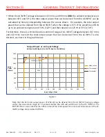
(* Power Derating to 80% below 90 Vrms)
Operating DC Input (Optional)
Voltage
22-33 V
Continuous Maximum Input Current
62 A
(full load, 22 V)
Transient Maximum Input Current
75 A
OUTPUT CHARACTERISTICS
Total Output Power Continuous
1250 W (1500 VA)
Maximum DC1 Output Power
510 W
Maximum DC2 Output Power
1250 W
(Note: Available AC power is reduced by power delivered to the DC output)
AC Output
AC Output Waveform
Pure Sinusoidal
Voltage
115 Vrms ± 3%
230 Vrms ± 3%
Frequency
60 Hz ± 0.5%
50 Hz ± 0.5%
400 Hz ± 0.5%
Instantaneous Peak Load Current
26 A (115 Vrms)
13 A (230 Vrms)
Load Power Factor
0-1.0
(leading or lagging)
Total Harmonic Distortion
2%
(1000W resistive load)
DC1 Output (optional)
Voltage Regulation (Over Load & Temperature) ± 3%
Common Voltage/Power combinations (DC1)
12 V at 42 A =504 W
(Other Options Available)
15 V at 34 A =510 W
24 V at 21 A =504 W
28 V at 18 A =504 W
40 V at 12.5 A =500 W
50 V at 10 A =500 W
DC2 Output (optional)
Voltage Setpoint
± 3%
No Sharing
Voltage Regulation (Over Load & Temperature) -2%
Common Voltage/Power combinations (DC2)
50 V at 20 A =1000 W
24 V at 50 A =1200 W
28 V at 44.6 A =1250 W
Droop Share
(Output droops vs. load to allow passive sharing among modules.)
24 V Option
Voltage Regulation (Over Load & Temperature) -15%
26 V at 0 A
22 V at 50 A =1100 W
28 V Option
Voltage Regulation (Over Load & Temperature) -13%
30 V at 0 A
26 V at 48.1 A =1250 W
ENVIRONMENTAL CHARACTERISTICS MIL-STD-810G
Temperature Methods 501.5, 502.5
Operating Temperature
-20 °C to +55 °C
Non-operating Temperature
-40 °C to +65 °C
Altitude Method 500.5
Operating
0 - 18,000 ft
Non-operating
0 - 40,000 ft
Environmental Tests
Shock/Drop
Method 516.6, Procedures 1,4,6
Temperature Shock
Method 503.5, Procedure 1
Vibration
Method 514.6, CAT 5, 7, 8, 9, 24
Fungus
Method 508.6
Salt Fog
Method 509.5
Sand and Dust
Method 510.5, Procedures 1,2
Rain
Method 506.5 Procedure 1
Humidity
Method 507.5 Procedure 2
Mechanical Vibrations of
Method 528 Procedure 1
Shipboard Equipment
RELIABILITY CHARACTERISTICS MIL-HDBK-217F
MTBF 100 kHrs
MIL-217F Ground Benign, Ta=25 °C
ELECTROMAGNETIC CAPABILITY MIL-STD-461F
CE101
30 Hz - 10 kHz
CE102
10 kHz - 10 MHz
CS101
30 Hz - 150 kHz
CS106
10 kHz - 40 GHz
CS114
10 kHz - 200 MHz
CS116
10 kHz - 100 MHz
RE101
30 Hz - 100 kHz
RE102
10 kHz - 18 GHz
RS101
30 Hz - 100 kHz
RS103
2 MHz - 40 GHz
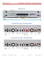
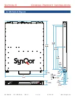
MECHANICAL CHARACTERISTICS
1U Standard Battery Pack Chassis
Chassis Size
17.00”W x 21.60”D x 1.73”(1U)H
Case Material
Aluminum
Total Weight
32 lbs. (with chassis & battery)
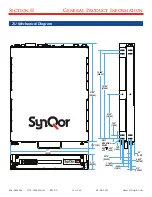
Optional 2U Extended Internal Battery Pack
Chassis Size
17.00”W x 21.60”D x 3.33”(2U)H
Case Material
Aluminum
Total Weight
50 lbs. (with chassis & battery)
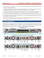
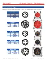
Connectors
AC Input Connector
MS3470L14-4P
User I/O Ports
HD DB15 Female
Configuration I/O Port
HD DB15 Male
Ethernet Port
Amphenol RJF22N00, Code B
DC Input Connector
MS3470L18-8P
AC Output Connector
MS3470L14-4S
DC1 Output Connector
MS3470L14-4SW
DC2 Output Connector
MS3470L18-8S
Cooling Exhaust Fans
Sound Pressure Level (SPL)
54 dB(A)
Air Flow
0.67(m
3
/min) 23.7 CFM
Two fans in system, above specs are for each fan separately.