CHAPTER TWO
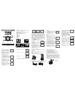
Rear View TM7000
Figure 2.4
INPUT: 85-264VAC (47-440 Hz)
Fuse: 1.0A@100-120VAC 0.5A@220-
240VAC
J1
M1
M3
M2
M4
Serial
Model
TMC7000
Made in USA
J11
J12
J10
J9
J2
J3
J4
J5
J6
J7
J8
FUSE
DRAWER
ON/OFF
SUITCH
AC INPUT
OPTION AREA
RS-232
TALKER
RS-232 I/O
IRIG B AC
CODE OUT
IRIG B DC
CODE OUT
MULTICODE
AC CODE OUT
MISCELLANEOUS OUTPUTS
MULTICODE DC CODE OUT
EXT. TIME
BASE INPUT
CODE
INPUT
CODE
OUTPUT
PULSE/
1PPS INPUT
2.5
OPTION CARD INSTALLATION PROCEDURE
The following procedure should be adhered to when installing any option card assembly:
a.
Disconnect power from the TymMachine.
b.
Option cards are installed in the rear panel option areas labeled M1 to M4.
Remove the six screws that hold the Rear Panel Option Plate and the Option Plate
Blanks to the chassis. Refer to Figure 2.4.
c.
Configure and verify the settings of the option card. Refer to the Option
Description supplied with the card or furnished in Appendix A of this User’s
Guide.
d.
Insert the module into the selected option slot, being careful that the components
are on the upper side of the module. Make sure the option card is firmly seated in
the connector.
e.
Reinstall the Rear Panel Option Plate. Using the six screws, attach the Option
Plate (furnished with the Option Card) and any remaining blank panels through
the Rear Panel Option Plate to the metal chassis card guides.
f.
Attach any applicable I/O cables, and apply power to the unit.
2-6
TM7000 TymMachine TCG/T (Rev D)
Symmetricom, Inc.


