3. Make sure the computer or accessory you are
connecting to the PTC is also turned off.
4. The accessory connector on the PTC’s left
side is protected by a rubber plug. Pull up on
the bottom of the plug to reveal the accessory
connector.
Note: The top of the rubber plug is perma-
nently attached to the PTC.
5. Examine the PTC’s accessory connector and
the modular RJ-41 connector on the end of
the adapter cable. The connector on the cable
has a tab that must line up with the slot in
the PTC’s accessory connector.
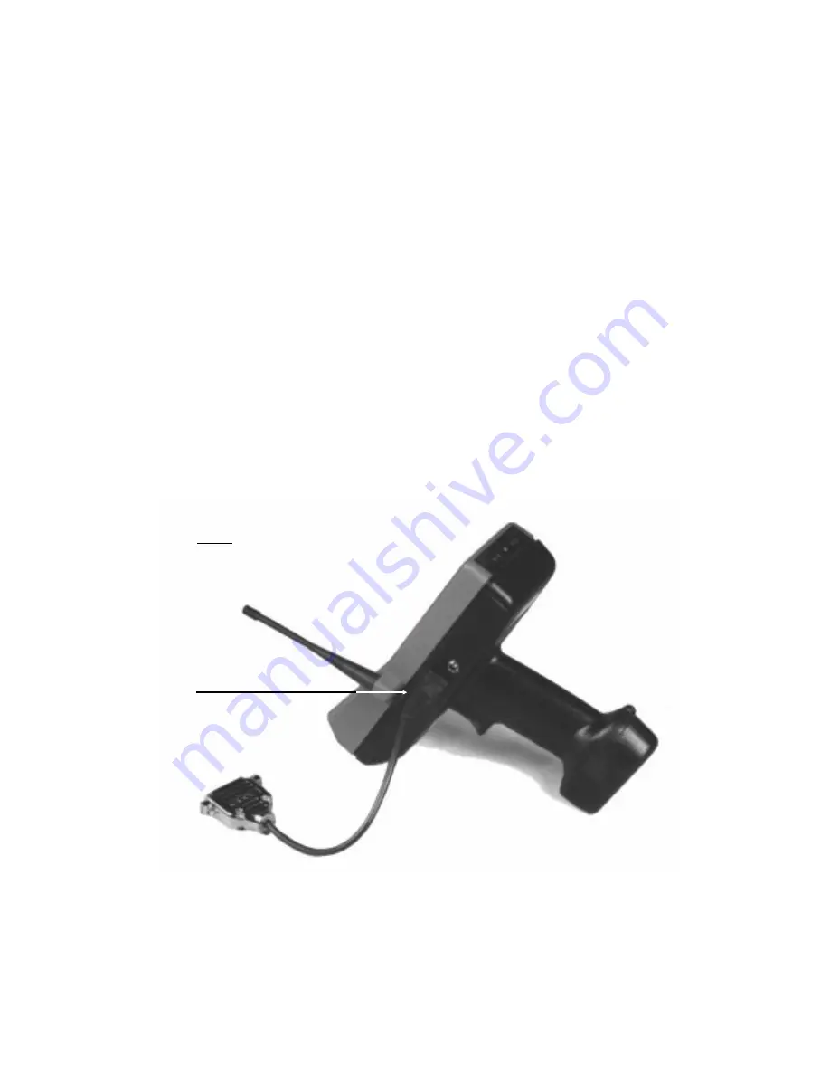
6. Gently slip the connector on the cable into
the accessory connector until the tab on the
cable’s connector clicks into place. See Figure 2.
PLUG THE ADAPTER CABLE’S
MODULAR CONNECTOR INTO THE
PTC’S ACCESSORY CONNECTOR
FIGURE 2
Connecting a cable
35


