background image


18 

Section 03 

Technical Description 


Line system 

The MIURA RS has A, B and C- line 

levels, which fork twice from the 
bottom (riser) to the top (canopy) and 

which are divided into main, middle 

and top lines. The individual line levels 
are connected with one another using 

the “handshake knot”

The Maintenance and Service book has 

a detailed line connection plan, 
showing the individual levels, 
connections and line descriptions. 
With the brake lines, the individual 
levels are bundled at the end with the 

main brake line. This runs through the 
brake pulley on the riser and is knotted 

at the brake swivel of the control 
handle. There is a mark on the main 

brake line which allows the control 
handle to be correctly positioned. 
The main lines are all attached to 

Maillon quick links. The lines are fed 
through special elastic rings and 

attached to prevent them from 

slipping and to ensure that they sit in 
the correct position. 

Risers 


WARNING 

The paraglider is delivered ex factory 

with the Maillon quick links secured 
using a strong thread-locking 
compound Loctite

©

 to prevent 

unintentional opening. After service 
work, quick links which have been 

opened must be secured again 
against unintentional opening. 

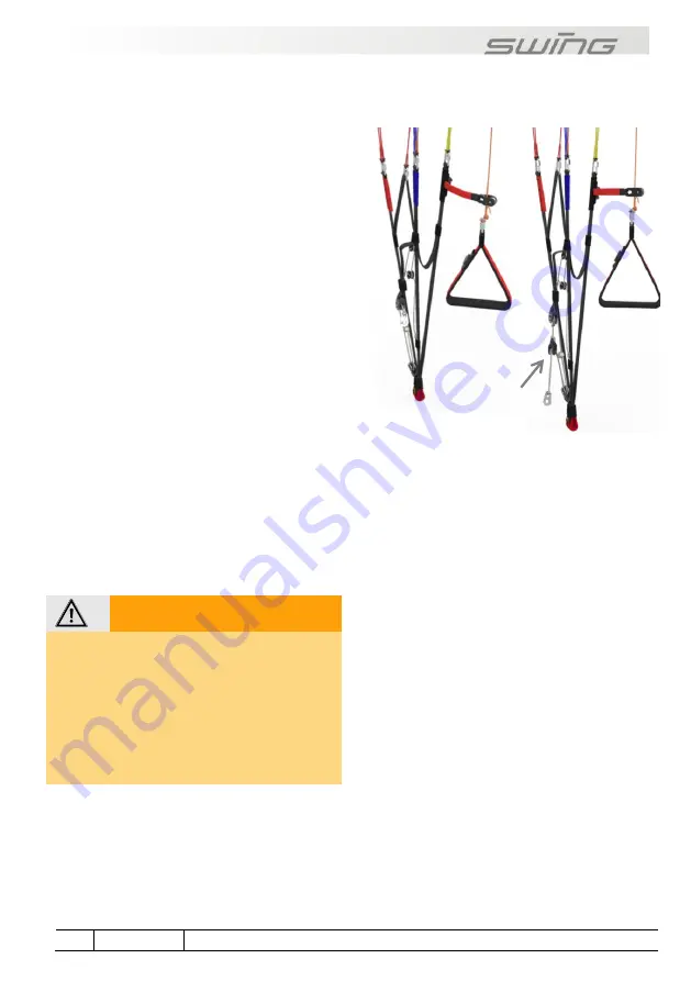
The 12mm wide risers, specially 
developed for the MIURA RS with 

Kevlar reinforcement allow the pilot to 

adjust the speed of the MIURA RS 
using a pulley system to suit his/her 
individual preference. 

There is more information on using the 

speed s

ystem in the section “Flying the 

MIURA RS

”.


Fig. 3


MIURA RS 

riser without 
speed limiter 

Fig. 4


MIURA 

RSe riser 

with speed 
limiter 


Summary of Contents for MIURA RS

Page 1: ......

Page 2: ......

Page 3: ...st rate materials and high quality workmanship of your paraglider set it apart from others Your SWING paraglider was developed to comply with all of the current safety and certification requirements in Germany To enhance your flying enjoyment further we recommend that you familiarise yourself with the information and instructions contained in this Manual regarding safety equipment and service If y...

Page 4: ...s to the Manual There is further information about the SWING website in the section SWING on the World Wide Web Express written consent from SWING Flugsportgeräte GmbH is required for any duplication of this Manual in whole or in part with the exception of short quotations in specialist articles and in any form or by any means whether it be electronic or mechanical The fact that this Manual has be...

Page 5: ...e 13 Disclaimer and exclusion of liability 13 Operating limits 14 GLIDER CATEGORIES AND GUIDELINES 14 EN LTF certification 15 Target group and recommended flying experience 15 Suitability for training 15 03 TECHNICAL DESCRIPTION 16 GENERAL LAYOUT ILLUSTRATION 16 MIURA RS ONE GLIDER TWO CLASSES 16 Top of the class 16 Thermalling expert 16 RAST 17 LINE SYSTEM 18 RISERS 18 TECHNICAL DATA 19 04 SETTIN...

Page 6: ...em 34 TANDEM PARAGLIDING 35 AEROBATICS 35 07 MOTORISED FLIGHT 36 DGAC 36 TECHNICAL DATA 36 RISERS 37 TRIMMER 37 SUITABLE DRIVES 38 LAUNCH CHECK 38 LAUNCH 39 Forwards launch 39 Reverse launch 39 CLIMBING 40 COUNTER TORQUE OSCILLATION 40 CRUISING 41 Level flight 41 Turns using the main brake 41 Countering the torque effect 41 LANDING 41 Landing with stationary propeller 42 Landing with motor running...

Page 7: ...oring and transporting the glider 49 LOOKING AFTER THE PARAGLIDER 49 Handle with care 49 Dampness humidity 50 Contact with salt water 51 Sand and salt air 51 Cleaning 51 10 REPAIRS INSPECTIONS AND WARRANTY 52 TYPE DESIGNATION 52 SPAREPARTS 52 REPAIRS 52 Small repairs to the glider 52 SWING workshops 52 REGULAR INSPECTIONS 52 Lines 52 Quick brake line check 53 INSPECTION 54 General 54 Inspection pe...

Page 8: ...SWING Flugsportgeräte GmbH 57 Paraglider recycling 57 DHV 57 AIR Turquoise 57 DULV 57 VERSIONS 57 GLIDER DETAILS 58 PILOT DETAILS PROOF OF OWNERSHIP 58 INSPECTION AND REPAIRS CARRIED OUT 58 ...

Page 9: ...structions on getting started and using the paraglider 2 Maintenance and Service Book PDF Download Technical data and inspection information specific to the particular glider 3 Inspection Information PDF Download General instructions and guidance on carrying out the regular inspection of paragliders Special text DANGER Sections of text headed Danger indicate a situation where there is imminent dan...

Page 10: ... the part labelled follows the picture Bullet points Bullet points are used in the Manual for lists Example risers lines Paraglider manual on the internet Additional information about your paraglider and any updates to the Manual can be found on our website at www SWING de This Manual was current at the time of going to print This Manual can be downloaded from SWING s website prior to print SWING ...

Page 11: ...final stage of which is recycling in an environmentally friendly manner The synthetic materials used in a paraglider must be disposed of properly If you are not able to arrange appropriate disposal SWING will be happy to recycle the paraglider for you Send the glider with a short note to this effect to the address given in the Appendix ...

Page 12: ...nts are caused by pilots misjudging the weather for flying Paragliders themselves are extremely safe In the type certification tests all component parts of a paraglider must withstand eight times the load of normal flight There is a three fold safety margin compared to the maximum extreme load occurring in flight This is higher than the two fold margin usual in aviation Accidents caused by materia...

Page 13: ...nformation to be followed than was previously the case Disclaimer and exclusion of liability Operating limits Use of the paraglider is at the pilot s own risk The manufacturer cannot be held liable for any personal injury or material damage which arises in connection with SWING paragliders The certification and warranty shall be rendered invalid if there are changes of any kind incl paraglider des...

Page 14: ...ature is below 30 C or above 50 C the glider is used for aerobatics extreme flying or flight manoeuvres at an angle greater than 135 there have been modifications to the canopy lines or risers which have not been approved Glider categories and guidelines WARNING The descriptions of flight characteristics contained in this Manual are all based on experiences from the test flights which were carried...

Page 15: ...uding pilots under instruction The pilot should already have basic knowledge of how to use a paraglider Target group and recommended flying experience The target group for the MIURA RS extends from ambitious student pilots right through to cross country pilots who fly for enjoyment Pilots will be impressed by its excellent properties in thermal flying its high level of passive safety and its very ...

Page 16: ...tive performance data that would appeal to pilots who are already licensed We achieved this goal by using a modern canopy construction combined with a unique riser system which allows the pilot to choose between two different settings for speed system travel and thus two glider classifications also This means that the MIURA RS can be adapted according to pilot ability Thermalling expert The MIURA ...

Page 17: ... strengths into play effectively stabilising the canopy and gently calming turbulent air This makes the MIURA RS extremely stable and forgiving which results in noticeably improved precision and comfort during flight and consequently also more control and better performance for the pilot Collapse behaviour If there are any stability problems RAST prevents the canopy from suddenly and or completely...

Page 18: ...handle to be correctly positioned The main lines are all attached to Maillon quick links The lines are fed through special elastic rings and attached to prevent them from slipping and to ensure that they sit in the correct position Risers WARNING The paraglider is delivered ex factory with the Maillon quick links secured using a strong thread locking compound Loctite to prevent unintentional openi...

Page 19: ...kg 55 75 70 90 80 100 90 110 105 125 115 145 Wing area projected m 19 2 21 4 22 7 24 0 27 0 29 7 Wing span m 10 6 11 2 11 6 11 9 12 6 13 2 Number of cells 48 48 48 48 48 48 Number of riser 4 4 4 4 4 4 Maximum symmetrical control travel at maximum take off weight cm 55 60 60 65 65 65 Maximum speed system travel mm 145 100 145 100 145 100 145 100 145 100 145 Any data for the Miura RSe that differs i...

Page 20: ...ot The length of the break line must not be altered Factory settings Correctly installed brake lines have about 10cm of feed This is how far you must pull down the brakes before the trailing edge of the paraglider starts to move downwards and begins to brake Note that the brake cascades already cause drag by their aerodynamic resistance The factory setting for the MIURA RS is intended to allow opt...

Page 21: ...hange in launch or flight behaviour TIP Brake line length for the Miura RS can be easily checked by making a simple comparison with an A line There is further information on this in the section Quick brake line check Brake knots The overhand knot shown below is the most suitable for connecting the brake line to the brake handle WARNING Loose unsuitable or incorrectly tied brake line knots can caus...

Page 22: ...larly useful if there is a strong headwind for valley crossings or to leave a dangerous area quickly The A and B risers can be shortened using the speed bar This decreases the canopy s original angle of attack and the speed of the glider increases The speed system must be correctly fitted and adjusted to ensure it operates smoothly during flight Before first launch the length should be adjusted to...

Page 23: ...ystem is used to its full extent You will not be able to use the paraglider s full potential if the speed system is too long Fasten the speed bar to the harness before launch to avoid tripping over it when preparing to launch or taking off Fig 7 How the MIURA RS speed system works MIURA RS without speed limiter top figure MIURA RSe with speed limiter bottom figure ...

Page 24: ...ted the MIURA RS fully complies with the requirements for A classification The position of the stop ball must not be altered in order to guarantee this adjustment The optional speed limiter restricts speed system travel to the first stage Speed limiter The MIURA RS gives pilots the option of limiting speed system travel An additional pulley is fitted at the speed system s top pulley and the speed ...

Page 25: ...to take off weight pilot weight including clothing glider harness and equipment Determine your take off weight by weighing yourself with all of your equipment and your backpack The MIURA RS must be flown within the permitted weight range In addition to the permitted weight range Swing gives a recommended weight range for the MIURA RS The flight characteristics of the MIURA RS are particularly well...

Page 26: ...ing flight In particular extreme flying and behaviour in spirals can become much more demanding if ballast is not positioned correctly Reserve It is a mandatory requirement to carry an approved reserve for use in emergency situations where the paraglider fails and recovery is not possible for example after colliding with another aerial sports craft In choosing a reserve you should be careful that ...

Page 27: ...eserves in front containers This means that the flight behaviour in the particular paraglider harness combination selected by the pilot can differ significantly from that documented in the certification test report The illustration below shows the influence different harness geometries have on flight behaviour Bear in mind your own personal preferences when choosing a harness Fig 11 Overview of di...

Page 28: ...NING If there are obvious folds in the glider because it has been tightly packed or stored away for a long time then the pilot should carry out some practice inflations before first launch and smooth out the leading edge a little This ensures that the flow profile is correct during launch It is particularly important in low temperatures that the leading edge is smoothed out 5 point check The 5 poi...

Page 29: ... of the canopy and to carry out fine tuning so is therefore recommended in strong winds WARNING The pilot must work actively to keep the glider on the ground in higher wind speeds from approx 6 m s otherwise the glider may rise above the pilot unintentionally PLEASE NOTE When reverse launching or when ground handling be careful not to loop the brake lines through the risers because this can damage...

Page 30: ...d the pilot must compensate for the changed flight behaviour by pulling carefully on the risers You will find further information about steering with back risers in section C bridge system Rapid descent methods Many flying situations call for a very rapid descent to avoid a dangerous situation e g the upcurrent from a cumulus cloud an approaching cold front or a storm front Rapid descent methods s...

Page 31: ...an cause the wing to climb become unsettled or partly collapse Recovery can be assisted by braking lightly on the outside DANGER Under certain conditions it may be necessary to brake the outside half of the wing and or to use weight shifting to recover from the spiral Furthermore for exiting the manoeuvre several turns with a corresponding loss of altitude may be required You must immediately depl...

Page 32: ...ded It is even possible to land using big ears for example on a top landing to compensate for the updraft The wing loading increases by the reduction in the wing s surface area the wing becomes more stable against collapses in turbulence Nevertheless the air resistance of the wing also increases and it flies more slowly and closer to the stall limit To counter this and to increase the effectivenes...

Page 33: ...recovery release the speed bar wait until the wing has slowed down and let go of both A risers Assist the opening process by a short impulsive pumping motion with the brakes if the ears do not open automatically Landing There are no specific characteristics to observe during landing Prepare for landing by making a straight approach flight into the wind and allow the glider to decelerate at trim sp...

Page 34: ...ct direction without braking the glider too much and stalling it Winch towing requires special training and special regulations must be observed These are The pilot must have completed the appropriate training and hold a licence The winch and release must have a certificate of compliance which covers the towing of paragliders The winch operator must have undertaken training which includes the towi...

Page 35: ...is important to ensure before first launch that it can be deployed without any obstruction If this is not the case then a suitable webbing release system should be used Tandem paragliding The MIURA RS does not have certification for use in tandem paragliding Aerobatics In Germany it is prohibited to perform aerobatics using a paraglider which under German law is included under the term aerial spor...

Page 36: ... motor risers with trimmers as these provide the pilot with a larger speed window as well as trim options during motor flight Technical data MIURA RS MIURA RSe XS S SM ML L Registration DGAC yes yes yes yes yes Take off weight min max kg 70 100 90 115 100 125 110 140 125 155 Trim speed km h 38 1 38 1 38 1 38 1 38 1 Accelerator no no no no no Trimmer yes yes yes yes yes Cruising speed Vno km h 45 2...

Page 37: ...e trimmers closed at all times DANGER Under no circumstances should the trimmer loops get caught in the main carabiners This would shorten the D risers considerably especially if the wing is not trimmed Fig 12 Trimmer loop in the main carabiner Blocked trimmer Free trimmer Fig 13 Trimmer block WARNING Use the trimmers only during powered flights Do not use the trimmers when flying through turbulen...

Page 38: ...anufacturer of the motor or by a pilot as an individual type test certification Launch Check The launch point check is carried out immediately before launch to check once again the most important safety points It should always be carried out in the same sequence so that nothing is overlooked These points are 1 Is the canopy arranged in a half moon shape and are all the air entrances open 2 Are all...

Page 39: ...is used Release the risers and accelerate until the MIURA RS takes off Take note of the following points during a forwards launch if the cage for the motor is not firmly in place the risers can shift it during take off and press it against the propeller make sure this has not happened before you fly at maximum power during launch use of the brakes should be smooth and moderate lightly brake the MI...

Page 40: ...er launch first fly into the wind and let the MIURA RS pick up speed Do not climb with too great an angle of attack Select the rev speed and brake line use so that there is enough speed to keep sufficient reserve before stall point If the angle of attack is too high when you are climbing the glider could stall if there is any further increase in the angle of attack e g a vertical gust A further re...

Page 41: ...ng control travel Turns against the counter torque require more brake line input than turns into the counter torque The MIURA RS has extremely low negative tendency so it can also be turned in a tight area by carefully pulling the inside brake line If the brakes are applied more the bank attitude increases and the glider will fly a fast turn increasing in steepness which will eventually become a s...

Page 42: ...r landing Landing with motor running Prepare for a landing with the motor running by making a straight final approach into the wind and allow the MIURA RS to level out with the motor running One meter above the ground pull down the brakes as far as they will go so that the glider is fully braked shortly before touching the ground Switch off the motor immediately after touching down Further tips on...

Page 43: ...a harness with the following dimensions Total weight in flight Width A Height B 80 kg 40 2 cm 40 1 cm 80 100 kg 44 2 cm 42 1 cm 100 kg 48 2 cm 44 1 cm If a harness different from the one used for the type test certification is used flight behaviour may vary from that described in this Manual Safety training Taking part in safety training is in principle advisable in order to familiarise yourself w...

Page 44: ...tric collapse Asymmetric collapses are caused by the stagnation point moving to the trailing edge of the glider A negative angle of attack makes part of the canopy collapse and tuck under and the glider may plunge down turn away or spin Recovery Should an asymmetric collapse occur counter brake slightly on the side of the glider that is still inflated to stop it turning away and to stabilise it un...

Page 45: ... that you can take immediate action to prevent it Deep stall Paragliders can go into a deep stall for a variety of reasons brake lines too short no slack old or damaged glider material which therefore has increased level of permeability altered trim line length and changes to profile characteristics caused by moisture e g flying in rain Paragliders have a particular tendency to stall if the wing l...

Page 46: ...h can result in airflow separation stall It is relevant here that if a glider absorbs more water as older gliders do because they lose their water repellent coating over time and is closer to the deep stall limit because of its design and age less water absorption and thus weight increase will put the glider into deep stall 2 When there is rain there can be so many water droplets on the top surfac...

Page 47: ...o the glider that the adhesive planned will not alter the glider s flight behaviour If you are in doubt we recommend that you do not attach the adhesive PLEASE NOTE Attaching adhesives to the glider which are large heavy or made of unsuitable material may result in revocation of the certification Overloading The glider structure is put under high levels of strain in particular on extreme flight ma...

Page 48: ...ore easily during flight creating an altered air inflow which can lead to a loss in performance and changes in flight behaviour The leading edge reinforcements also perform an important function on launch Therefore the less they have been bent the more easily the glider will inflate and launch PLEASE NOTE Make sure that the leading edge reinforcements lie flat and are not bent or twisted by doing ...

Page 49: ...raglider near radiators or other heat sources Always transport your glider in the special inner bag and use the backpack provided for the rest of the equipment Looking after the paraglider Handle with care The life of any paraglider depends to a large extent on how you treat it The MIURA RS is constructed in a weight optimised manner with heavier robust fabrics for the leading edge and lightweight...

Page 50: ...ven though it is very comfortable never sit on the backpack with the glider inside Lines The MIURA RS has various different high quality and accurately manufactured lines which have been selected according to the load and area of use You should also protect the lines from unnecessary UV light because as with the fabric UV light in particular will weaken the lines Be careful that there is no abrasi...

Page 51: ...oft sponge Use a weak soap solution for stubborn stains and then rinse it out carefully and thoroughly Leave the glider to dry in a place which is well ventilated and in the shade PLEASE NOTE Do not use chemicals brushes rough cloths high pressure cleaners or steamers to clean the glider as these can damage the fabric coating and weaken it The glider becomes porous and loses braking strength Do no...

Page 52: ...ingle replacement lines for the MIURA RS can be ordered direct from us at info swing de The replacement of complete groups of lines must be carried out by a SWING authorised workshop SWING workshops All repairs and servicing should be carried out by a SWING authorised workshop or directly by SWING SWING workshops have trained staff original SWING parts and the necessary know how all of which will ...

Page 53: ...en if the paraglider is used infrequently or not at all This can affect the safety and function of your paraglider Signs of wear are slight bumps or changes in flying characteristics The lines must then be replaced immediately WARNING A damaged line can result in loss of control of the glider Always replace lines which are damaged If you need to replace damaged or worn out parts use only original ...

Page 54: ...must be inspected as follows check the situation in your country All Gliders must be inspected every two years from the purchase date The glider must be inspected after 150 hours of use including ground handling if this occurs first Ground handling time must be at least doubled when calculating the total hours of use because of the increased wear and tear on the glider Validity of inspection It is...

Page 55: ...erms of the warranty are written on the website Go to the SWING website www SWING de Service Guarantee http www swing de guarantee html The manufacturer must be notified immediately of any defects in the product variations or changes in flight behaviour and any warranty claims If necessary the glider or other SWING product must be sent to SWING Flugsportgeräte GmbH for inspection ...

Page 56: ...n as is and as available basis SWING reserves the right to alter the websites at any time or to block access to them Facebook Twitter youtube SWING is very active with the new media of Facebook Twitter and youtube and has various websites which are updated daily on various topics related to aviation and SWING products SWING TV On SWING TV SWING puts official video footage and footage by pilots und...

Page 57: ...d Germany DHV Am Hoffeld 4 Postfach 88 83701 Gmund am Tegernsee Germany Tel 49 0 8022 9675 0 Fax 49 0 8022 9675 99 Email dhv dhv de www dhv de AIR Turquoise Route du Pré au Comte 8 1844 Villeneuve Switzerland Tel 41 0 21 965 65 65 https para test com DULV Deutscher Ultraleichtflugverband e V Mühlweg 9 71577 Großerlach Morbach Germany Tel 49 0 7192 93014 0 E mail info dulv de www dulv de Versions V...

Page 58: ...__ Check flight date __ __ __ __ 202__ Mark and signature ________________________________________ Pilot details Proof of ownership Name Address Telephone Email Inspection and repairs carried out Date Work carried out General condition on delivery Completed by Name Stamp and signature ...

Page 59: ...Notes ...

Page 60: ......

Reviews: