MAINTENANCE
126
Loadings on Coupling Heads, Overrun
Assemblies and Axles
The permitted ‘nose’ weights of the coupling
head/stabiliser, overrun assembly and
drawbars, must never exceed the lowest value
stamped on the assemblies.
Fig. 1
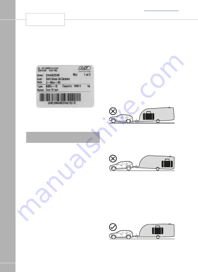
The maximum axle loading is that stamped on
the plate (Fig. 1 example axle plate) located in
the centre of the axle, facing rearwards.
Note:
Do not attempt to remove as this will
void the plate.
The third line down marked “Capacity” is the
maximum permitted axle loading and must not
be exceeded.
The caravan manufacturer may have stated a
lower maximum loading weight on the plate
fitted adjacent to the entrance door, this then
becomes the maximum permitted load and
must not be exceeded. We recommend you
record the Axle details for future reference.
It may be possible if required for the caravans
MTPLM to be upgraded.
Your caravan dealer will require the following
details from the axle plate.
(Example of information ref Fig 1)
• Order - CHA402248
• Qty – 1 of 2
• Date - 3 May 05
• Type - B850-10
• Capacity - 1000E
Please consult your Swift Group Dealer to
confirm if this is possible.
Loading
Loads to be carried in the caravan should be
placed directly over, or as close as possible
to the axles, otherwise the handling will be
impaired. Maximum gross weight, as advised
by the caravan manufacturer, must not be
exceeded without approval from AL-KO.
Maximum loading is defined as the difference
between ex-works weight and the permitted
total weight.
Load Too Far Forward (Fig 2)
Steering and braking ability reduced. Increased
loading on the rear axle and chassis of the
tow vehicle.
Fig. 2
Load Too Far Back (Fig. 3)
High skid risk together with poor braking
effect.
Fig. 3
Load Over Axle (Fig 4)
Optimum road holding together with maximum
braking effect. Exceptionally heavy loads
should be placed directly over the axle.
Attention should be paid to the legal
regulations regarding the permitted pressure
exerted by the towbar on the towed unit.
Fig. 4
LOADINGS
Summary of Contents for Basecamp 2018
Page 1: ...Swift Group Owner s Handbook Basecamp Issued July 2017 CREATING SMILES FOR LIFE ...
Page 48: ...S E RVICE S 46 GAS SCHEMATIC Gas schematic Back to section menu ...
Page 141: ...MA INT E NA N CE 140 WIRING DIAGRAM ROAD LIGHTING Back to section menu ...
Page 142: ...MA INT E NA NCE 141 WIRING DIAGRAM CONSUMER CIRCUITS Back to section menu ...
Page 143: ...MA INT E NA N CE 142 WIRING DIAGRAM CONSUMER CIRCUITS ROOF Back to section menu ...
Page 144: ...MA INT E NA NCE 143 WIRING DIAGRAM POWER CIRCUITS Back to section menu ...
Page 145: ...MA INT E NA N CE 144 WIRING DIAGRAM 230V CIRCUITS Back to section menu ...
Page 146: ...MA INT E NA NCE 145 WIRING DIAGRAM 13 PIN SOCKET Back to section menu ...
Page 147: ...MA INT E NA N CE 146 WIRING DIAGRAM CABLE COLOUR CHART Back to section menu ...


