Bringing the Benefits of Real-Time Data Collection to the World
Sutron Corporation, 22400 Davis Drive, Sterling, Virginia 20164
9
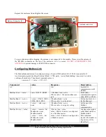
Replace the enclosure lid and tighten the screws
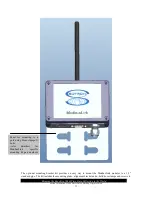
To prevent damage while shipping, the antenna is not connected to the module. Please screw the antenna to
the RP-SMA connector on the top of the enclosure, till it is secure.
DO NOT OVERTIGHTEN THE
ANTENNA
to prevent damage to the RP-SMA connector.
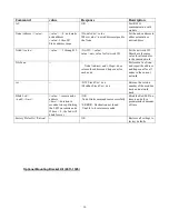
Configuring ModbusLink
The ModusLink module can be configured using a 10-pin to DB9 cable (6411-1382-24) connected to J5.
Any terminal program like HyperTerminal (Baud = 5700, parity = none, Handshaking = none) can be used to
configure the modules. The general command syntax is
<command> = <value><CR><LF>
Command
value
Response
Description
AT
--
OK
Test RS232
communication with
module
Modbus Com = <
value>
value
= RS232, RS485
> Modbus Com =
value
Where value = the new modbus com
port
Set Modbus
communication port to
either RS85 or RS232
Modbus Baud =
<value>
<value>
=57600 , 38400 ,
19200, 9600, 4800
>Modbus Baud =
value
Where value = new baud rate
Set the baud rate for
the Modbus port
Modbus Parity =
<value>
<value>
= odd, even,
none
>Modbus Parity =
value
Where value = new parity setting
Set the parity for
Modbus
communication
Modbus Device = <
value
>
<value> =
master : Set
Modbus device as
ModbusLink-M
<value> =
slave : Set
Modbus device as
ModbusLink-S
>Device type =
value
value = Master if device is configured
as a Modbus master
value = slave if device is configured as
a Modbus master
Configure the module
as ModbusLink-M or
ModbusLink-S
(this command
requires the module to
be power cycled to
take effect)
Battery Connector (J5)
Antenna connector
Summary of Contents for ModbusLink-M
Page 2: ......

