background image

OPERATING


PROCEDURES

26

                                                                                                         OP CIC1200E Rev4.0 06-09   Chapter 4

4

4.9.  Calibration of the Built-In 

UV Intensity Meter

Calibrate the built-in UV intensity meter using the 
SUSS UV Intensity Meter (UV1000) and the UV 
probe 405[nm] as an external reference.

• Open the shutter of the lamp house.

• Measure the actual UV intensity with the SUSS 

UV Intensity Meter equipped with a correspond-
ing probe head by placing it in the center of the 
chuck. Remember the actual reading of the 
meter - better: write it down.


• Now connect probe head to the socket of the CIC 

labeled UV-PROBE. Place it in the same position 
as before. (better: Leave it after Step2) Activate 
the calibration mode with key CALIB (press key 
for 1-2 sec) Press CALIB until the display reads 
UVPR. Press START. The alphanumeric display 
shows UVP and the corresponding value of the 
measured light intensity.


• Check reading of the alphanumeric display (step 

3) and compare it with the value for the light in-

tensity obtained in step 2. If necessary adjust the 
value for the LIGHT INTENSITY with the trim-
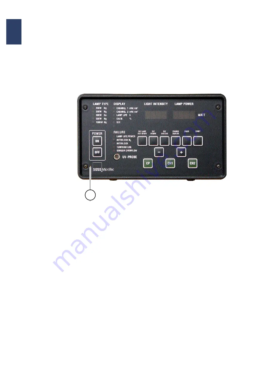
ming potentiometer (see adjacent picture). Cali-
bration is accomplished when the numerical 
value of the light intensity as given by the refer-
ence meter (step2) is equal to the reading of the 
alphanumeric display LIGHT INTENSITY of the 
CIC1200

Control Panel of the CIC1200

The calibration point (potentiometer) for the built-in
UV Intensity Meter is indicated by „1“.

1

Summary of Contents for CIC1200

Page 1: ...USER MANUAL Constant Intensity Controller CIC1200 Rev4 0 06 09 www suss com...

Page 2: ......

Page 3: ...SUSS MicroTec s customers only and cannot be used for distribution reproduction or sale without the express written permission of SUSS MicroTec This information may be incorporated into the user s do...

Page 4: ...DISCLAIMER AND PUBLISHING DETAILS II DISCLAIMER i...

Page 5: ...3 Program Parameters 9 4 Operating Procedures 11 4 1 CIC1200 Front Panel 11 4 1 1 The Annunciator Group FAILURE 12 4 2 CIC1200 Rear Panel 13 4 3 Power Supply Stand by 14 4 4 Selecting the Exposure Lam...

Page 6: ...l CI Mode 25 4 9 Calibration of the Built In UV Intensity Meter 26 4 10 Additional Functions 27 4 10 1 Full Reset 27 4 11 Switching Off the Lamp 27 5 Maintenance and Service 29 5 1 Maintenance 29 5 2...

Page 7: ...of the SUSS equipment or machinery the CIC is inte grated in Additional training can be provided on request The CIC does not contain any user serviceable parts see 5 2 Service and Installation Mainten...

Page 8: ...when the host machine e g mask aligner is deactivated but in stand by 1 4 1 Fuse Replacement Where necessary deactivate and lock off the host machine and remove machine covers or panels to access the...

Page 9: ...y relay A sample of a safety circuit is shown below For fur ther details refer to the manuals of the host machine or contact SUSS service Lamp House Door Interlock Sample from SUSS MA BA8 Opening the...

Page 10: ...amp data sheets and SUSS machine manuals for proper lamp orientation Warning The ignition unit is a complex electrical component producing high voltage pulses for lamp ignition Repair must be done by...

Page 11: ...ld and vaporized when hot After lamp breakage immediate decontamination is mandatory because mercury represents a potential serious threat to health and pollutes the environ ment Follow recommended st...

Page 12: ...er is equipped with light guards enclosing UV lamp and exposure path The equipment shall not be operated unless all of these protective covers and devices are in place Personnel entrusted with the adj...

Page 13: ...x power 1600W Exchangeable fuses in rear panel 2x 10A slow blow 5x20 mm Optical Sensor for CI mode Dual channel using silicon photodiodes with thin film dielectric or selected glass absorption filters...

Page 14: ...Type Part Number SUSS Usable with SUSS Lamp House LH 200W Hg Osram HBO 200W DC 191806 LH250 LH350 LH1000 LH1500 Ushio USH 250 S 169722 LH NFH 350W Hg Osram HBO350W S 146049 LH350 LH1000 LH1500 Ushio...

Page 15: ...l after power has been switched off During this period of time the lamp cannot be started Left alphanumeric display shows message COOL Right alphanumeric display shows time left before exposure lamp c...

Page 16: ...PROGRAM PARAMETERS 10 OP CIC1200E Rev4 0 06 09 Chapter 3 3...

Page 17: ...ory confirm with SET LAMP To erase press or and confirm with SET LAMP Power ON ON S SS REA X XX DY SW revision Display Lamp Hours CHANGE DIS PLAY X HRS Choose Constant Power Mode CP WAIT S TART Ignite...

Page 18: ...oup DIS PLAY with CHANGE DISPLAY from Channel 1 to Channel 2 Choose Constant Intensity Mode CI MODE CH1 or CH2 XXXX XXXX Calibration and adjust ment of intensity Set CH1 CH2 has to be done before Adju...

Page 19: ...1200 Front Panel Annunciator Groups 1 2 3 4 1 Annunciator Group LAMP TYPE 2 Annunciator Group DISPLAY 3 Annunciator Group FAILURE 4 Alphanumeric Display for LIGHT INTENSITY and LAMP POWER 5 Key Pad se...

Page 20: ...lash dur ing normal operation the UV lamp should be turned off and replaced to prevent explosion Refer to the Operator s Manual of the machine for instructions on lamp re placement Note As long as the...

Page 21: ...CIC1200 E Rev4 0 06 09 Chapter 4 13 4 4 2 CIC1200 Rear Panel 1 Main Power with Fuses T10 A 2 Remote Start 3 RS232 4 Control IN OUT 5 External Alarm 6 Optical Sensor 7 Lamp Interlock 8 Lamp Cooling In...

Page 22: ...nd of damage for the machine Lamps driven by wrong voltage or cur rent could not only become inoperable but may explode Explosion would destroy optical com ponents and release mercury vapors Only lamp...

Page 23: ...e power supply If used adequately it prevents overshoot ing of the lamp lifetime Overstretching the lamp duty causes in general heavy degradation of lamp performance The risk for lamp explosion rises...

Page 24: ...c tion 4 6 2 of the present manual Note All calibration is done in CP Mode 4 5 2 Operating Mode CH1 CH1 stands for Constant Intensity Channel 1 The exposure lamp is run in constant light intensity mod...

Page 25: ...isplay e g SUSS 2 00 Finally the alphanumeric display shows the mes sage READY The LEDs of the annunciator group LAMP TYPE 350W is ON Actuate the key CP The alphanumeric display now shows the message...

Page 26: ...on the lamp type has become op erational The alphanumeric display labeled LAMP POWER shows the message XXXX W To run the lamp in IDLE mode actuate the key IDLE The display shows IDLE XXX W In IDLE mo...

Page 27: ...ivate the SET mode In the annunciator group FAILURE the LED adjacent to LAMP LIFE POWER is flashing With the keys or enter desired numerical value for the power the alphanumeric display LAMP POWER rea...

Page 28: ...E DISPLAY Each time one activates this key the next LED will be activated as shown in the sequence below CHANNEL 1 XXX mW cm2 The alphanumeric display labeled LIGHT INTENSI TY reads the numerical valu...

Page 29: ...s sensing e g 13 0 mW cm2 Each measurement is labeled with a digit from 1 to 17 The alphanumeric display labeled LAMP POW ER shows the current reading in progress the measured value for the light inte...

Page 30: ...ight intensity of the UV light beam it is necessary to use a calibrated UV in tensity meter whose probes band pass filters should be identical to those of the optical sen sors used with the CIC contro...

Page 31: ...SUSS service engi neers or by experienced electricians The top cover of the CIC hold in place by 4 screws must be detached Adjustment potentiometers for CH1 and CH2 can be seen in the middle right abo...

Page 32: ...EL 2 CALIB Press START _ _ _ _ UVPR CHANNEL 1 CALIB To leave this menu press CALIB _ FINISH _ Press 8x CALIB 4 7 4 4 CAL1 RES Meaning RESet CALibration data Channel 1 Press 8x CALIB 4 7 4 5 CAL2 RES M...

Page 33: ...CH2 for about 1 2 sec and store the values displayed a high pitched beep will be heard confirming the operator that the parameters have been stored Now one can run the CIC1200 in Constant Intensity M...

Page 34: ...better Leave it after Step2 Activate the calibration mode with key CALIB press key for 1 2 sec Press CALIB until the display reads UVPR Press START The alphanumeric display shows UVP and the correspon...

Page 35: ...g Off the Lamp To switch off the lamp press button OFF on left of the CIC front panel The lamp will be switched off imme diately The CIC itself will be still in stand by mode with an internal timer co...

Page 36: ...OPERATING PROCEDURES 28 OP CIC1200E Rev4 0 06 09 Chapter 4 4...

Page 37: ...warm up period of the new lamp check for correct cooling conditions exhaust tempera ture and lamp socket temperature For details see section Lamp cooling in the Installation Manual of the respective...

Page 38: ...ock active PWR ERR Power Error Lamp power could not reach Pmin or Pidle during COLD phase N2 ERR Nitrogen cooling Error N2 Loss is active for a few seconds FAILURE LED INTERLOCK N2 blinks INT ERR Cont...

Page 39: ...the Constant Intensity Con troller that can not be resolved by control settings or lamp exchanges call for further assistance at nearest SUSS MicroTec office see SUSS Micro Tec Worldwide at the end o...

Page 40: ...MAINTENANCE AND SERVICE 32 OP CIC1200E Rev4 0 06 09 Chapter 5 5...

Page 41: ......

Page 42: ...am dong Gangnam gu Seoul 135 984 Korea Phone 82 0 2 2008 4656 Fax 82 0 2 2008 4555 SUSS MicroTec Singapore The Comtech 60 Alexandra Terrace 02 21 118502 Singapore Singapore Phone 65 627 173 53 Fax 65...

Reviews: