


Chapter 3 Getting Started with the SR-TRITON16Ni
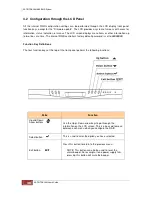
3.1 Connecting the SR-TRITON16Ni to your Network
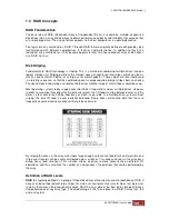
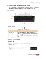
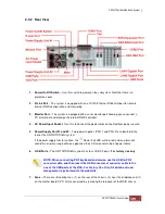
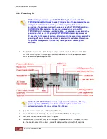
1. For the purpose of initially configuring, monitoring and remote notification of the internal RAID
controller, attach a network cable to the R-Link port on the rear of the SR-TRITON16Ni
chassis. Connect the other end to your network hub or switch. Alternatively, you may use the
RAID controller’s serial monitor port to initially configure the internal RAID controller, but you
will still need the R-Link port attached to your IP network for remote notification via SMTP,
SNMP protocols. Connect the included null modem serial cable from the RAID system’s serial
monitor port to any available COM port of a workstation or server. The internal RAID
controller’s R-Link port IP address is shipped set for
DHCP
and will display the DHCP IP
address on the LCD front panel (If restore defaults is performed on the internal RAID
controller or a DHCP server is not available the IP with be default to
172.16.0.2
), otherwise
you can set hard set the IP address via the SR-TRITON16Ni LCD front panel or through the
RAID controller’s serial monitor port. The serial monitor port terminal setting are as follows;
115200, 8, 1, flow control = none
. The “
x
” and then “
enter”
key is the break sequence.
Internal RAID controller’s
Login = admin, password = 00000000
.
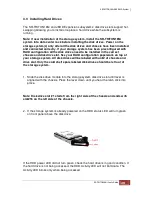
Note: The first volume will be dedicated to the proNAS operating system and needs to
be at lease 200GBs in size and RAID1 RAID level (proNASVG). It is recommended to
dedicate a two disk drive RAID set be used for larger environments. Typically this has
already been done by Partners Data Systems along with the data RAID volumes and
can be skipped to the next step. After initially setting up the internal RAID controller
RAID volumes you need the reboot the SR-TRITON16Ni system before continuing with
the next step before the proNAS operating system can any disk volumes.
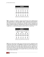
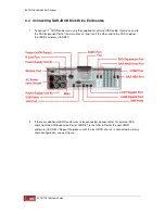
2. To initially setup the SR-TRITON16Ni’s data ports, temporally attach a network crossover
cable to the LAN0 (eth0) Ethernet data port on the rear of the SR-TRITON16Ni subsystem.
Connect the other end to a laptop or workstation’s Ethernet port setup to be on the same
network.
The default IP address for LAN0 is 172.16.0.1, subnet 255.255.0.0
. The second
Ethernet LAN1 port is disabled by default and can be setup to be trunked with LAN0 or be
used to connect to another SR-TRITON16Ni for replication or High availability solutions.
LAN1 (eth1) also shared with the SR-TRITON16Ni motherboard
IPMI (BMC) for remote
power control and monitoring of motherboard components
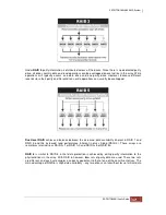
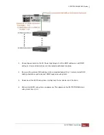
. The proNAS management
requires JAVA to be installed in your workstation or server and will install a JAVA component
automatically into your workstation or server OS. After powering on your SR-TRITON16Ni
and it completes its power on diagnostics, using an internet browser, type into the address
field the default IP address
172.16.0.1
. The proNAS login screen will appear. The SR-
TRITON proNAS operating system administrator
Login = admin, password = 00000000.
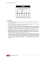
After which the data and management ports can be modified for your network. Both data ports
and IPMI motherboard IP address setup steps are explained in further detail later in this User
guide. You must use either cat5e or cat6 shielded Ethernet cables for best performance.
Summary of Contents for TRITON 16Ni
Page 1: ...SurfRAID TRITON 16Ni User s Guide Revision 1 1...
Page 40: ......
Page 41: ......
Page 42: ......
Page 43: ......
Page 67: ...5 3 7 Stop Volume Check Use this option to stop current running Check Volume Set process...
Page 111: ...4 Verify the new LV size...
Page 135: ...4 The iSCSI logical volume capacity is extended...
Page 236: ...2 Select Set LAN Configuration and press Enter key 3 Setup LAN Configuration...
Page 247: ......