


10
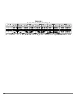
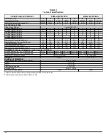
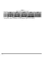
TABLE 1
Technical Specifications
Power (Kw) (
xx
)
10
15
18
20
23
20
23
27
Net capacity (BTU/h)
34120
51180
61420
68240
78480
68240
78480
92130
Heating temperature rise range (F)
1
40-50
45-60
50-75
55-75
60-80
55-75
60-80
60-80
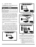
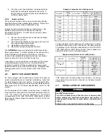
ELECTRICAL SYSTEM
Volts - Hertz - Phase
Electrical element #1 (Kw)
5
5
4
5
4
5
4
5
Electrical element #2 (Kw)
5
5
5
5
5
5
5
5
Electrical element #3 (Kw)
5
4
5
4
5
4
5
Electrical element #4 (Kw)
5
5
5
5
5
4
Electrical element #5 (Kw)
5
5
4
Electrical element #6 (Kw)
4
Blower motor Consumption (Amp)
3.3
3.3
3.3
3.3
3.3
6.9
6.9
6.9
Heating Elements Consumption (Amp)
41
61
74
82
94
82
94
111
Total Consumption (Amp)
44.3
64.3
77.3
85.3
97.3
88.9
100.9
117.9
Circuit amperage (wire sizing)
2
55
80
97
107
122
111
126
147
Maximum size circuit breaker (Amp)
2
60
80
100
110
125
125
150
150
BLOWER DATA (factory adjusted to a static pressure of 0.5" W.C.)
Blower speed at 0.50" W.C. static pressure
LOW
MED-LOW MED-LOW MED-HIGH MED-HIGH MED-LOW MED-LOW MED-LOW
Blower speed at 0.20" W.C. static pressure
LOW
MED-LOW MED-LOW MED-LOW MED-HIGH MED-LOW MED-LOW MED-LOW
Motor (HP) / number of speeds
Blower size
GENERAL INFORMATION
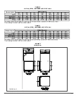
Overall dimensions (width x depth x height)
Supply
Return
Filter quantity and size
Shipping weight
Maximum cooling capacity
1) Select a blower speed that will generate the specified temperature rise
(1) 20" x 20"
2) Calculated on the basis of Norm C22.2 Nr.236
RATINGS AND PERFORMANCE
20" x 20" x 36.5"
15" x 18"
19" x 19"
G10-8
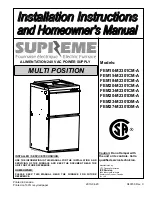
FEMxx -M2301CM-A
1/3 HP / 4 speeds
GT12-10
FEMxx -M2301DM-A
2 wires 240 - 60 - 1
1 HP / 4 speeds
5 tons
3 tons
48 Kg / 105 lbs
Summary of Contents for FEM10-M2301CM-A
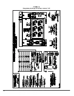
Page 12: ...12 FIGURE 6 Diagramme lectrique 10 kW avec moteur 1 3 HP...
Page 13: ...13 FIGURE 7 Diagramme lectrique 15 kW avec moteur 1 3 HP...
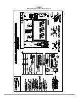
Page 14: ...14 FIGURE 8 Diagramme lectrique 18 kW avec moteur 1 3 HP et 20 kW avec moteur 1 3 HP et 1 HP...
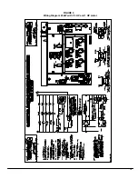
Page 15: ...15 FIGURE 9 Diagramme lectrique 23 kW avec moteur 1 3 HP et 1 HP...
Page 16: ...16 FIGURE 10 Diagramme lectrique 27 kW avec moteur 1 HP...
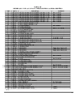
Page 17: ...17 COMPOSANTES ET PI CES DE REMPLACEMENT...
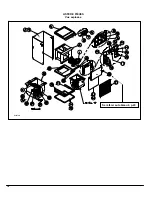
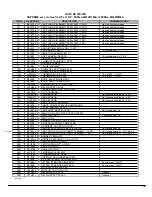
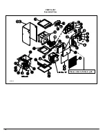
Page 18: ...18 LISTE DE PI CES Vue explos e B50079B Se r f rer au tableau 4 p 20...
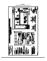
Page 32: ...12 FIGURE 6 Wiring Diagram 10 kW with 1 3 HP motor...
Page 33: ...13 FIGURE 7 Wiring Diagram 15 kW with 1 3 HP motor...
Page 34: ...14 FIGURE 8 Wiring Diagram 18 kW with 1 3 HP motor and 20 kW with 1 3 HP and 1 HP motor...
Page 35: ...15 FIGURE 9 Wiring Diagram 23 kW with 1 3 HP and 1 HP motor...
Page 36: ...16 FIGURE 10 Wiring Diagram 27 kW with 1 HP motor...
Page 37: ...17 COMPONENTS AND REPLACEMENT PARTS...
Page 38: ...18 PARTS LIST Exploded View B50079A Please refer to Table 4 p 20...