


19
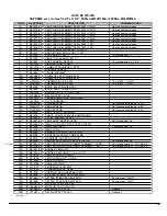
LISTE DE PIÈCES
SUPRÊME avec moteur 1/3 HP et 1 HP : FEMxx-M2301
C
M-A et FEMxx-M2301
D
M-A
ITEM
No DESSIN
DESCRIPTION
COMMENTAIRES
1A
B03274-01
ASS PLAQUE ELEMENT FEM-10kW (1/3 HP)
Hautes limites incluses
1B
B03275-01
ASS PLAQUE ELEMENT FEM-15kW (1/3 HP)
Hautes limites incluses
1C
B03276-01
ASS PLAQUE ELEMENT FEM-18kW (1/3 HP)
Hautes limites incluses
1D
B03276-02
ASS PLAQUE ELEMENT FEM-20kW (1/3 HP)
Hautes limites incluses
1E
B03277-01
ASS PLAQUE ELEMENT FEM-23kW (1/3 HP)
Hautes limites incluses
1F
B03317-01
ASS PLAQUE ELEMENT FEM-27kW (1 HP)
Hautes limites incluses
1G
B03276-02
ASS PLAQUE ELEMENT FEM-20kW (1 HP)
Hautes limites incluses
1H
B03314-01
ASS PLAQUE ELEMENT FEM-23kW (1 HP)
Hautes limites incluses
2A
B03273
ASS SEPARATEUR AVANT (1/3 HP)
2B
B03313
ASS SEPARATEUR AVANT (1 HP)
3
B03260
ASS CABINET EN "U"
Comprend item 4
4
B03302
ISOLATION CABINET EN "U"
5
B03263
ASS PANNEAU DESSUS
Comprend items 6, 7 & 8
6
L01J001
DISJONCTEUR 15 AMP
7
L07F015
COMMUTATEUR BASC. SPDT
8
L01L006
LUMIERE TEMOIN
9
B03286
CACHE ELEMENT
10A
L99H008
ELEMENT ELECTRIQUE 5kW
10B
L99H009
ELEMENT ELECTRIQUE 4kW
11A
R02N015
THERMODISC L150-55F
10 à 23kW - 1/3 HP
11B
R02N019
THERMODISC L140-55F
23 à 27kW - 1.0 HP
12
B03288
BOITE ELECTRIQUE HAUT
13
B03289
BOITE ELECTRIQUE COTE
14
L05F004
BORNIER A VIS, 4 POSITIONS
15
L01H009
RELAIS SPDT 24 VAC
16
L01F010
TRANSFORMATEUR 240/24Volts
17
L99F004
BLOC TERMINAL
18A
R02N016
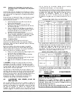
SEQUENCEUR
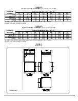
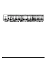
Se référer au tableau 4, p.20
18B
R02N017
SEQUENCEUR
Se référer au tableau 4, p.20
18C
R02N018
SEQUENCEUR
Se référer au tableau 4, p.20
19
B03265
ASS SUPPORT BORNIER
20
B03280
PORTE COMPARTIMENT ELECTRIQUE
21
Z04F004
FILTRE PAPIER 20 x 20 x 1
22
B03257-01
ASS PORTE VENTILATEUR
Comprend item 23
23
B02293-22
ISOLATION, ASS PORTE VENTILATEUR
24
B03258
ASS PLANCHER
Comprend item 25
25
B02293-21
ISOLATION
26
B03299
EMBOUT SUPPORT DE FILTRE
27
B03298
CONTOUR SUPPORT DE FILTRE
28
B30513
GLISSIERE DU VENTILATEUR
29
B03264
ASS SEPARATEUR DU VENTILATEUR
Comprend item 28
30A
B03301-03
ASS VENTILATEUR DE REMPLACEMENT (1/3 HP)
Comprend items 31, 32, 34 & 38
30B
B03318-03
ASS VENTILATEUR DE REMPLACEMENT (1 HP)
Comprend items 31, 32, 34 & 38
31A
B01291-04
BANDE SCELLANTE
31B
B01291-01
BANDE SCELLANTE 1 1/2" x 13 1/8"
32A
Z01I002
VENTILATEUR G10-8DD
32B
Z01I008
VENTILATEUR GT12-10DD
33A
Z01L001
AUBE G10-8DD
33B
Z01L003
AUBE G12-10DD
34A
L01I001
CONDENSATEUR 5 MF
34B
L01I003
CONDENSATEUR 10 MF
35
B01024
SUPPORT DE CONDENSATEUR
36
B03508
KIT ELECTRIQUE "VENTILATEUR"
37A
B01888
PATTES ET BANDES MOTEUR
Pour moteur 1/3 HP
37B
B01889
PATTES ET BANDES MOTEUR
Pour moteur 1.0 HP
38A
L06G013
MOTEUR 1/3 HP 240 VAC
38B
L06K005
MOTEUR 1.0 HP 240 VAC
39A
L01H009
RELAIS SPDT 24 VAC
Optionel
39B
L01H011
RELAIS SPDT 120 VAC
Optionel
r
B50079B
Summary of Contents for FEM10-M2301CM-A
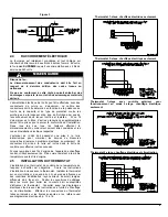
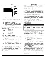
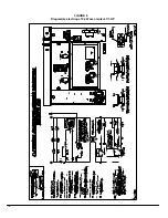
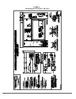
Page 12: ...12 FIGURE 6 Diagramme lectrique 10 kW avec moteur 1 3 HP...
Page 13: ...13 FIGURE 7 Diagramme lectrique 15 kW avec moteur 1 3 HP...
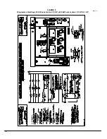
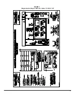
Page 14: ...14 FIGURE 8 Diagramme lectrique 18 kW avec moteur 1 3 HP et 20 kW avec moteur 1 3 HP et 1 HP...
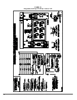
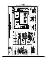
Page 15: ...15 FIGURE 9 Diagramme lectrique 23 kW avec moteur 1 3 HP et 1 HP...
Page 16: ...16 FIGURE 10 Diagramme lectrique 27 kW avec moteur 1 HP...
Page 17: ...17 COMPOSANTES ET PI CES DE REMPLACEMENT...
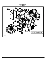
Page 18: ...18 LISTE DE PI CES Vue explos e B50079B Se r f rer au tableau 4 p 20...
Page 32: ...12 FIGURE 6 Wiring Diagram 10 kW with 1 3 HP motor...
Page 33: ...13 FIGURE 7 Wiring Diagram 15 kW with 1 3 HP motor...
Page 34: ...14 FIGURE 8 Wiring Diagram 18 kW with 1 3 HP motor and 20 kW with 1 3 HP and 1 HP motor...
Page 35: ...15 FIGURE 9 Wiring Diagram 23 kW with 1 3 HP and 1 HP motor...
Page 36: ...16 FIGURE 10 Wiring Diagram 27 kW with 1 HP motor...
Page 37: ...17 COMPONENTS AND REPLACEMENT PARTS...
Page 38: ...18 PARTS LIST Exploded View B50079A Please refer to Table 4 p 20...