Installation
14
Relay connection
Fail Safe Lock
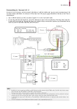
In order to use the Fail Safe Lock, connect N/C relay as shown in the figure below. There is normally a current flowing through the
relay for the Fail Safe Lock. When the relay is activated, blocking the current flow, the door will open. If the power supply to the
product is cut off due to a power failure or an external factor, the door will open.
NOTE
•
Install a diode at both sides of the door lock wire as shown in the figure to protect the relay from the reverse current, which occurs
when the door lock operates.
•
Take caution of the installation direction of the diode. Install the diode close to the door lock.
•
Use a separate power supply for BioStation L2 and the door lock.
Fail Secure Lock
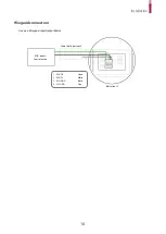
In order to use the Fail Secure Lock, connect N/O relay as shown in the figure below There is normally no current flowing through
the relay for the Fail Secure Lock. When the current flow is activated by the relay, the door will open. If the power supply to the
product is cut off due to a power failure or an external factor, the door will lock.
NOTE
•
Install a diode at both sides of the door lock wire as shown in the figure to protect the relay from the reverse current, which occurs
when the door lock operates.
•
Take caution of the installation direction of the diode. Install the diode close to the door lock.
•
Use a separate power supply for BioStation L2 and the door lock.
BioStation L2
1 - RLY NO
White
2 - RLY COM
Blue
Dead bolt /
Door strike
DC power
BioStation L2
Dead bolt /
Door strike
DC power
2 - RLY COM
Blue
3 - RLY NC
Orange


