C-4
SC510T Chassis Manual
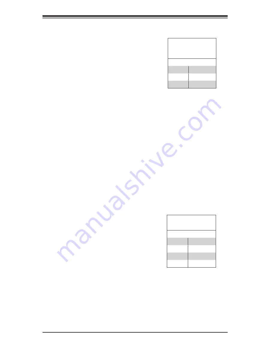
C-5 Front Connector and Pin Definitions
Backplane
Main Power
4-Pin Connector
(JP10)
Pin# Definition
1
+12V
2 and 3
Ground
4
+5V
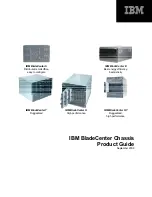
ACT_IN JP2
Pin# Definition
1
ACT_IN 0
2
ACT_IN 1
3
N/A
4
N/A
1. Power Connector
The 4-pin connector designated JP10 provides
power to the backplane. See the table on the
right for pin definitions.
2. - 3. SATA Connector
The SATA ports are used to connect the SATA
drive cables. The two ports are designated #0
and #1. Each port is also compatible with SATA
and SAS drives.
4. LED Input Connector (Not included on
most models)
This option only functions with the AOC-SATAR1
RAID controller.
5. ACT_IN Connector
The activity LED header, designated JP2, is used
to indicate the activity status of each drive.


