


50
X11SSV-M4F User's Manual
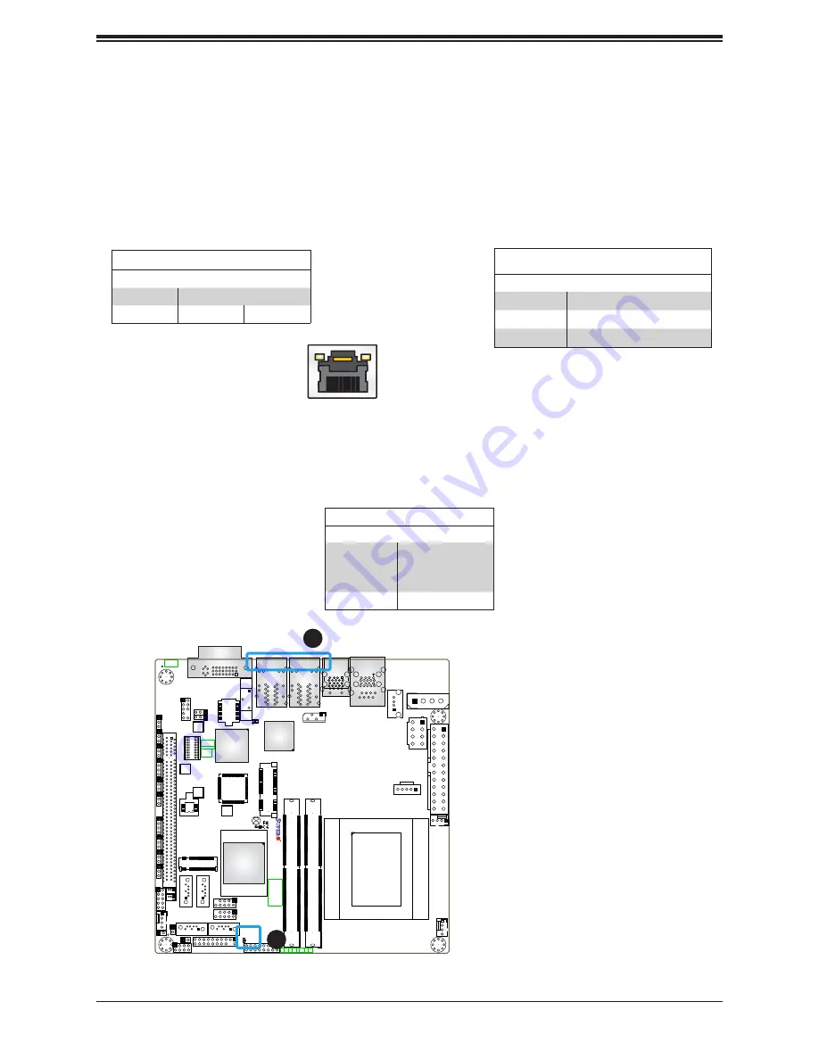
2.8 LED Indicators
LAN Port LEDs
The Ethernet ports located beside the DVI-A port have two LEDs. Each port has two LED
indicators. The Activity LED is yellow and indicates connection and activity. The Link LED
may be green, amber, or off to indicate the speed of the connection. Refer to the tables below
for more information.
Link LED
LED Color
Definition
Off
No Connection or 10 Mb/s
Green
100 Mb/s
Amber
1 Gb/s
JF1
JPW1
JPW2
JTPM1
JSD1
JSD2
X1
1SSV
-M4F
REV
:1.00
DESIGNED IN USA
FAN2
FAN1
FAN3
JP1
BT1
I-SATA4
I-SATA3
I-SATA2
I-SATA1
JPCIE1 x16
1
J17
JL1
J16
1
JSMB1
JD1
JPG1
JP
AC1
JI2C1
JI2C2
JWD1
JVRM1
JVRM2
JPUSB1
JBR1
JPME1
JGPIO1
I-SGPIO1
1
SRW1
SRW3
JPI2C1
A
LED2
C
LED1
A
SRW2
JBT1
JIPMB1
CPU
NIC3
FF
PWR
FAIL
AUDIO
1-2:ENABLE
2-3:DISABLE
JPAC1:AUDIO
SATA DOM
+POWER
DVI-A
JI2C1/
1-2:ENABLE
JWD1:
JSMB1:SMBus1
2-3:DISABLE
1-2:RST
WATCH DOG
2-3:NMI
M.2
JI2C2:
USB7/8
USB5/6
JPUSB1:
USB0/1 WAKE UP
1-2:ENABLE
2-3:DISABLE
JD1:
4-7:SPEAKER
1-2:NORMAL
JPME1:
1-3:PWR LED
JBR1
1-2:NORMAL
RECOVERY
2-3:ME
RECOVERY
2-3:BIOS
PWR
LED
LAN3/4
LAN1/2
m-PCIE
NIC
HDD
LED
NIC
2
1
DIMMA1
DIMMB1
OH
PWR
ON
RST
KB/MS
USB3/4
USB1/2
USB9
COM1
SRW4
Aspeed
AST2400
Intel
I350-AM2
Intel
CM236
1
1. Onboard Power LED
2. LAN Port LED
2
Onboard Power LED
LED2 is an Onboard Power LED. When this LED is lit, it means power is present on the
motherboard. Turn off the system and unplug the power cord before removing or installing
components.
Onboard Power LED Indicator
LED Color
Definition
Off
System Off
(power cable not
connected)
Green
System On
Activity Indicator
Color
Status
Definition
Off
No Connection
Yellow
Flashing
Active
Activity LED
Link LED


