


Chapter 5: Advanced Motherboard Setup
5-21
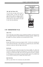
5-10 SAS/SATA/M.2 Ports
SATA Ports
This motherboard has six SATA 3.0 ports. I-SATA0 and I-SATA1 have built-in power
pins to support Supermicro's SATA DOM (Disk On Module) solutions. I-SATA4 is via
the JMD1 M.2 connector, I-SATA5 is via the JMP1 Mini PCI-E slot.
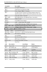
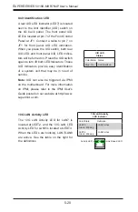
10G LAN Link Status LED
The 10G LAN Link status LED for LAN7 is
located at LEDT1, and the 10G LAN Link
status LED for LAN8 is located at LEDT3.
When the LEDs are on, LAN7/LAN8 are
working properly. See the table on the right
for the colors and definitions.
10G LAN Link Status
LED Indicator
Color/State Definition
LEDT1
Green: On
LAN7 Normal
LEDT3
Green: On
LAN8 Normal
LEDT1
LEDT3
SAS Ports
Sixteen SAS 2.0/SATA 3.0 ports are located at JSAS1 ~ JSAS4 on the motherboard
via four Mini-SAS HD cables. These SAS ports are supported by the LSI2116 SAS
controller and provide serial-link signal connections.
M.2 Socket
M.2 is formerly known as Next Generation Form Factor (NGFF). The JMD1 M.2
connector is designed for internal mounting devices. The X10SDV series deploys
an M key only dedicated for SSD devices with the ultimate performance capability
in a PCI Express 3.0 X4 interface for native PCIe SSD support. The X10SDV M.2
is mux with the I-SATA4 port for legacy SATA SSD devices.
Mini PCI-E Slot
JMP1 is a mini PCI-E 2.0 X1 slot that is mux with I-SATA5.
Summary of Contents for SUPERSERVER 5018D-MHR7N4P
Page 1: ...SUPERSERVER 5018D MHR7N4P USER S MANUAL 1 0 ...
Page 5: ...Notes Preface v ...
Page 14: ...1 6 SUPERSERVER 5018D MHR7N4P User s Manual Notes ...
Page 116: ...7 40 SUPERSERVER 5018D MHR7N4P User s Manual Notes ...
Page 118: ...A 2 SUPERSERVER 5018D MHR7N4P User s Manual Notes ...