


31
Appendix A: BPN-SAS3-825TQ Backplane
Backplane Main Power
4-Pin Connector
Pin# Definition
1
+12V
2 and 3
Ground
4
+5V
CD-ROM/FDD Power
4-Pin Connector
Pin# Definition
1
+5V
2 and 3
Ground
4
+12V
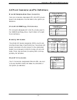
#1 and #2 Backplane Main Power Connectors
The 4-pin connectors, designated JP10, and JP13 provide
power to the backplane. See the table on the right for pin
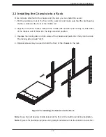
definitions.
#3 and #4 CD-ROM/Floppy Pin Connectors
Pin connectors designated J17 and J18, provide power to
the CD-ROM and floppy drives. See the table on the right
for pin definitions.
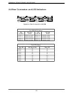
A.6 Front Connector and Pin Definitions
SAS Activity LED Header
Pin Definitions
Pin # Definition
Pin # Definition
1
ACT IN#0
6
ACT IN#4
2
ACT IN#1
7
ACT IN#5
3
ACT IN#2
8
ACT IN#6
4
ACT IN#3
9
ACT IN#7
5
Ground
10
Empty
#5 Activity LED Headers
The activity LED header, designated JP26 is used to indi-
cate the activity status of each SAS drive. The activity LED
header is located on the front panel. For the activity lead
header to work properly, connect to it using a 10-pin LED
cable. This is only used when the activity LED is not sup-
ported by the hard drive.
#6 and #7 I
2
C Connectors
The I
2
C Connectors, designated JP44 and JP45, are used
to monitor the HDD activity and status. See the table on
the right for pin definitions.
I
2
C Connector
Pin Definitions
Pin# Definition
1
Data
2
Ground
3
Clock
4
No Connection