Suntor ST30HPT User Manual Download Page 2

2nd

I. Disclaimer

SUNTOR is the registered trademark of SUNTOR ELECTRONICS CO., LIMITED. All product names and brands in this
manual are trademarks or registered trademarks of the Company. SUNTOR ELECTRONICS CO., LIMITED reserves all
copyrights of the product and the manual. All the information must not be copied or reproduced in any form without
permission of SUNTOR. There may be semantic differences between disclaimers of different languages. The Chinese
version shall prevail in Chinese mainland, while the English version shall prevail in other regions. Thank you for
purchasing SUNTOR ST30HPT. Please use ST30HPT according to local radio regulations. Before using, please carefully
read this disclaimer. Once the product is used, all the contents of the disclaimer will be regarded recognized and
accepted. Please install and operate the product in strictly accordance with the requirements of this manual.
SUNTOR ELECTRONICS CO., LIMITED and its affiliates will not assume any legal responsibility for results or losses
caused by improper use, installation, assembly and modification (including the use of non-specified SUNTOR parts
and accessories, such as the radio power amplifier, antenna and SMA extension cord).

II. Precautions for integration

1) Be sure to use the parts provided by SUNTOR.

2) Reverse connecting power line positive and negative will burn the device out.

3) Before powering on please make sure the antenna are in good connection and not install or remove the

antennas with power on.

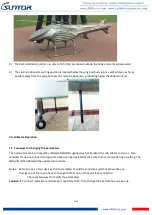
4) Given that the carbon fiber body and metal load may have shielding effects on antenna signals, they should not

be installed between the antenna and ground terminal. Keep the antenna on board free from winding or
blocking by obstacles. The antenna end should be vertically downward without bending to prevent shortening
communication distance and failure communication.

5) Antennas on board should be kept away from other radio antennas to avoid electromagnetic noise and

interference. We recommend to make full use of data and video transmitting function of ST30HPT to minimize
the radio devices quantity on board.

6) If using PTZ Camera, please do the PTZ self-testing firstly then connect HDMI cable.

7) HDMI cable and antenna on board may interfere with GPS. Please keep the HDMI cable and antenna away from

the GPS module and its cables.

8) Do not disassemble or modify SUNTOR ST30HPT. Any problem during installation, contact SUNTOR or SUNTOR

local branch office.

9) Keep appropriate distances between different electronic devices during installation to minimize the

electromagnetic interference.

10) Before using, please make sure all cables are in good connection and all components can work properly.

Summary of Contents for ST30HPT

Page 1: ...V Operating Instructions Steps 7th VI Antenna Installation 9th 1 Multi rotor UAV 9th 2 Fixed Wing UAV 9th VII Software Operation 10th 7 1 Two ways for changing the parameters 10th 7 2 How to use the s...

Page 2: ...sure to use the parts provided by SUNTOR 2 Reverse connecting power line positive and negative will burn the device out 3 Before powering on please make sure the antenna are in good connection and no...

Page 3: ...t the Futaba RF as OFF Through the S1 port uplink the PPM SBUS signal 16 Before using please check the power of RX and TX If the receiver power off transmitter on board will lose connection 17 Adjusti...

Page 4: ...x1 Ground antenna x1 DC power cable x2 TTL cable 2 HDMI video cable x2 Network cable x1 TTL to RS232 cable x2 Optional USB TTL serial port x1 SMA Cable Copper wire tinned shield semi soft line x2 TPa...

Page 5: ...One end XT30PW Male the other end DC female 1 2 S1 Serial Port 5P GH with lock socket GH 1 25mm we only use 4P 1 3 RF and HDMI Interface RF Standard SMA to connect with antenna or feeder cable HDMI I...

Page 6: ...mm 2 RX Interface Definition 2 1 Power Interface Power on off Pull type switch Power Connector XT30PW F Female Power Cable One end XT30PW Male the other end DC female GH 3P Signal Definition 1 TXD 2 G...

Page 7: ...ace Mini HDMI Port with camera Marker is video input Port with display marker is video output 2 4 S2 serial Port and Ethernet Port S2 SH 4P 1 0mm ETH non standard port Need to co work with lan card Et...

Page 8: ...ter and receiver The PWR indicator will bright and the whole system starts work 4 The status of all indicators during starting When the device begin to normally start work all indicators status is des...

Page 9: ...n UAV please refer the following description VI Antenna Installation 1 Multi rotor UAV 1 Using SMA metal shielded semi flexible blue feeder cable provided by SUNTOR to connect the TX SMA port with ant...

Page 10: ...parameters can be changed by software SUNTOR supplied such as bandwidth code stream and so on Two windows for device on board and ground station can be operated at the same time to do monitoring or se...

Page 11: ...he parameters of TX and RX are different now Secondly change the TX parameters After the changing is ok the communication will be successful again If you connect the PC with RX you need to change the...

Page 12: ...down of performance at selected rates If setting a fixed TX Rate It is recommended to retain a fade margin of at least 10 dbm for optimum performance For example for a link 8MHz channel with a signal...

Page 13: ...s a user to set the expected distance that the wireless signal needs to travel The TDD COFDM sets various internal timeouts to account for this travel time Longer distances will require a higher setti...

Page 14: ...ot be set into maximum but rather for the minimum value required to maintain an adequate system fade margin 7 2 3 RS1 Configuration In this section you can modify two parameters listed in the followin...

Page 15: ...Default 192 168 55 2 master 192 168 55 1 slave Remote Port UDP port of distant device mentioned above Default 20002 Listening Port UDP port which the IP Series listens to monitors UDP packets received...

Page 16: ...emote IP Addr to 192 168 55 5 7 2 6 RF New NET Configuration RF Net ID Each network of TDD COFDM modules must have a unique Network ID This Network ID must be set in each unit on the network RF Encryp...

Reviews: