Sunsea AIoT SIMCOM User Manual Download Page 10


SIMCOM_EVB Kit_User Guide_V1.02 


www.simcom.com      


10 / 22                          


3. Accessory Interface


3.1 Power Interface 

Pin 

Signal 

I/O 

Description 

Adapter input 

5V/2.0A DC source input 
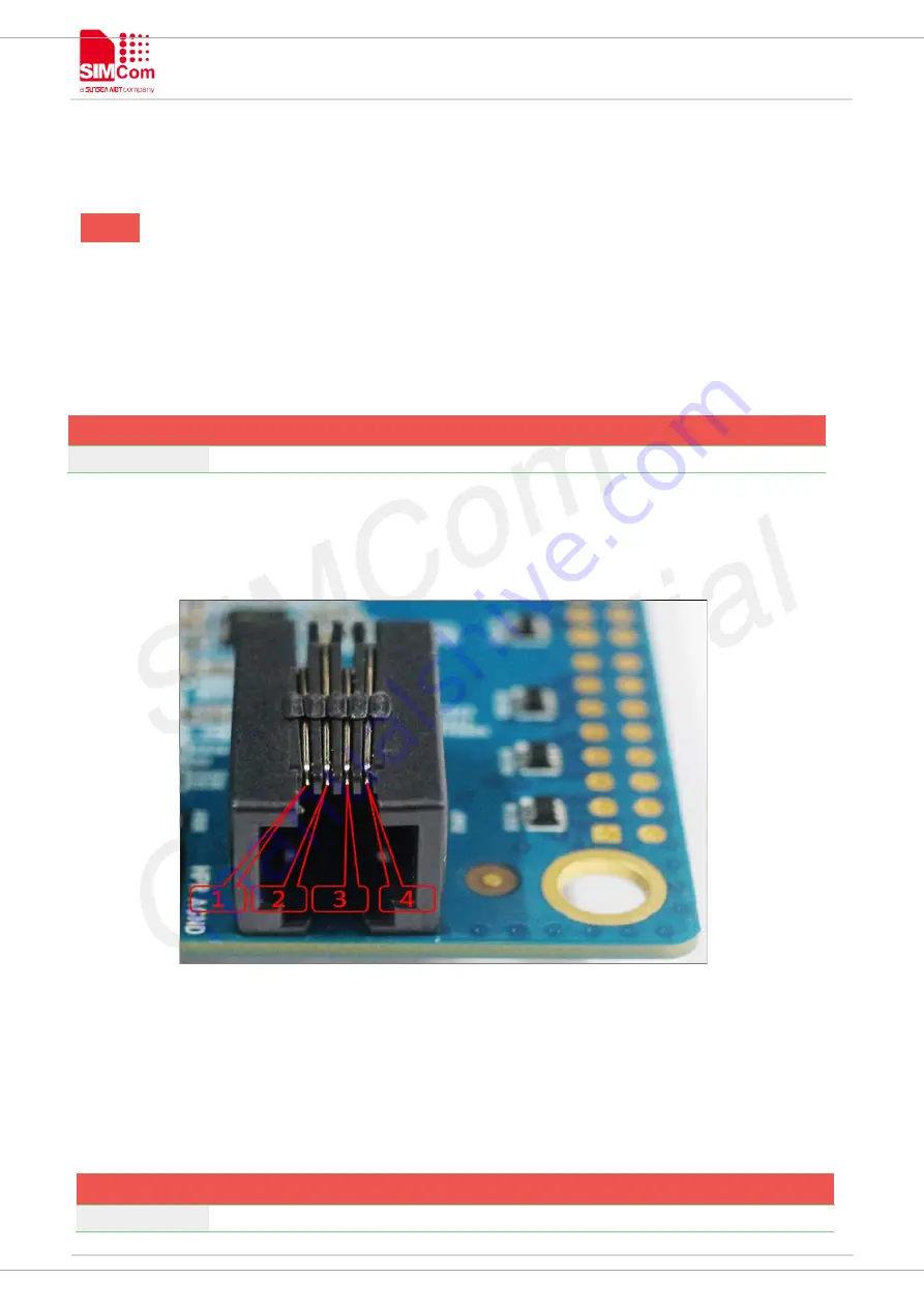


3.2 Audio Interface 


Figure4: Audio Interface 


Headset interface: 


Pin 

Signal 

I/O 

Description 

MICN 

Negative microphone input 

Summary of Contents for SIMCOM

Page 1: ...COM EVB Kit User Guide SIMCom Wireless Solutions Limited Building B SIM Technology Building No 633 Jinzhong Road Changning District Shanghai P R China Tel 86 21 31575100 support simcom com www simcom...

Page 2: ...ECT TO CHANGE COPYRIGHT THIS DOCUMENT CONTAINS PROPRIETARY TECHNICAL INFORMATION WHICH IS THE PROPERTY OF SIMCOM WIRELESS SOLUTIONS LIMITED COPYING TO OTHERS AND USING THIS DOCUMENT ARE FORBIDDEN WITH...

Page 3: ...om com 3 22 Version History Date Version Description of change Author 2016 07 12 1 00 Origin shijie yuan 2016 08 17 1 01 1 Update earphone shijie yuan 2 Add LED indicator for Status shijie yuan 2020 0...

Page 4: ...2 Audio Interface 10 3 3 SIM Card Interface 11 3 4 USB Interface 11 3 5 Power Switch 12 3 6 POWER_ON Button 12 3 7 RF Switch 12 3 8 LED Indicator 12 4 Test Interface 13 4 1 Test Point A 13 4 2 Test P...

Page 5: ...FIGURE2 SIMCOM EVB BOTTOM VIEW 7 FIGURE3 EVB ACCESSORY 9 FIGURE4 AUDIO INTERFACE 10 FIGURE5 VIRTUALSERIAL PORT 11 FIGURE6 TEST INTERFACE OVERVIEW 13 FIGURE7 TEST POINT A 13 FIGURE8 TEST POINT B 14 FIG...

Page 6: ...V1 02 www simcom com 6 22 SCOPE THIS DOCUMENT DESCRIBES HOW TO USE SIMCOM EVB TO DO TEST USER CAN GET USEFUL INFO ABOUT THE SIMCOM EVB QUICKLY THROUGH THIS DOCUMENT THIS DOCUMENT IS SUBJECT TO CHANGE...

Page 7: ...SIMCOM_EVB Kit_User Guide_V1 02 www simcom com 7 22 1 SIMCom EVB Overview Figure1 SIMCom EVB TOP view Figure2 SIMCOM EVB BOTTOM view...

Page 8: ...D Power switch E RF switch F TE connector G TE connector H SIMcard holder 1 I LED indicator for Netlight J LED indicator for Power K Test Point L Studs and nuts M mark of TE Module direction N LED in...

Page 9: ...SIMCOM_EVB Kit_User Guide_V1 02 www simcom com 9 22 2 EVB Accessory Figure3 EVB Accessory A SIMCOM EVB B 5V DC adapter C USB Cable D GSM WCDMA LTE antenna...

Page 10: ...om 10 22 3 Accessory Interface 3 1 Power Interface Pin Signal I O Description 1 Adapter input I 5V 2 0A DC source input 3 2 Audio Interface Figure4 Audio Interface Headset interface Pin Signal I O Des...

Page 11: ...terface SIMCard holder 1 J202 is the main holder SIM2 J203 is for special module which supports dual sim 3 4 USB Interface EVB USB interface A could be imaged to two virtual ports Figure5 Virtualseria...

Page 12: ...ll blink 3 7 RF Switch RF switch S401 could control module RF on or off That s hardware control of flight mode When RF on flight mode is off when RF switch off flight mode is on 3 8 LED Indicator LED...

Page 13: ...Point A Test point A Pin description Pin Signal I O Description 1 PWRKEY I Power on key 2 RESET I Reset key 3 DBG_RXD I Receive data 4 DBG_TXD O Transmit data 5 RI O Ring Indicator 6 DCD O Data carri...

Page 14: ...ndicator for NET Light 4 2 Test Point B Figure8 Test Point B Test point B Pin description Pin Signal I O Description 1 STATUS O Module working on indicate 2 NC17 3 KBC0 I KEYPAD input 4 5 6 KBC1 I KEY...

Page 15: ...l I O Description 1 KBR4 I KEYPAD input 2 SPI_CS O SPI Chip Select 3 SPI_MOSI O SPI Data output 4 DSR O Data Set Ready 5 SPI_MISO I SPI Data input 6 SPI_CLK O SPI Clock output 7 PWM1 O PWM output 8 PW...

Page 16: ...nd referenced current sink 4 COEX1 O RF synchronizing between Wi Fi and LTE 5 F LIGHT O Flight mode 6 SIM2_DET I SIM detect 7 COEX2 O RF synchronizing between Wi Fi and LTE 8 HOST_WAKE O HOST WAKEUP 9...

Page 17: ...WAKEUP_IN I O GPIO 3 NC11 AI Ground referenced current sink 4 RESERVED O RF synchronizing between Wi Fi and LTE 5 NC16 O Flight mode 6 NC3 I SIM detect 7 NC4 O RF synchronizing between Wi Fi and LTE...

Page 18: ...SIMCOM_EVB Kit_User Guide_V1 02 www simcom com 18 22 please refer to specified TE schematic for test point if there has difference...

Page 19: ...s on board near connectors It s easy to put TE in correct position without making mistake 2 take care of TE SMA connector direction 3 take care of the mark for TE direction on EVB board Uninstall and...

Page 20: ...light D402 will be bright and the LED light D401will blink at a certain frequency Through the state of LED you can judge registering status of the module For detailed description please refer to SIMCO...

Page 21: ...SIMCOM_EVB Kit_User Guide_V1 02 www simcom com 21 22 b configure right com port...

Page 22: ...SIMCOM_EVB Kit_User Guide_V1 02 www simcom com 22 22 c configure baudrate d Lastly connect the module and make a call...

Reviews: