background image

ENGLISH

XENON 2 FF                                                                                                        59  


Rev.3.0

Pelvic Restraint Belt continued

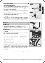
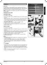
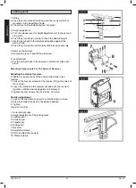
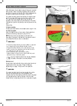
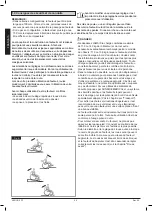
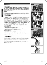
When fastened check space between the pelvic restraint 

belt and user. When correctly adjusted it should not be 

possible to insert more than the flat of the hand between 

the pelvic restraint belt and the user, (Fig.6.15.7).
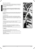
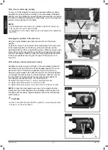
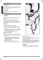
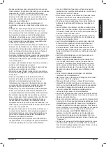
The pelvic restraint belt should be fixed so that the belt 

sits at an angle of 45 degrees across the user's pelvis. 

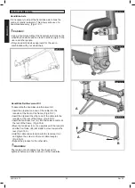
The user should be upright and be as far back as 

possible in the seat when correctly adjusted. The pelvic 

restraint belt should not allow the user to slip down in the 

seat,

(Fig.6.15.8).

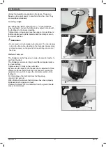
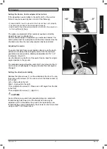
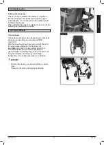
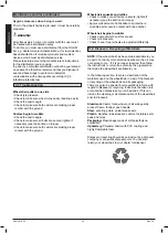
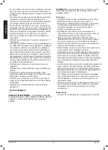
To fasten buckle: 

Firmly push male buckle into female buckle, (Fig.6.15.9).

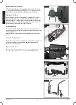
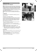
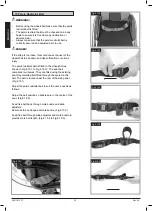
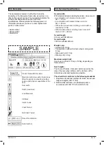
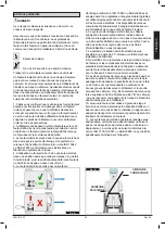
To release buckle:


Press the RED button in the centre of the buckle then 

pull the two halves gently apart, (Fig.6.15.10).

NOTE:

 If you have any questions on the use and 

operation of the pelvic restraint belt, the please contact 

your wheelchair dealer, carer or attendant.

WARNINGS!

• 

The pelvic restraint belt must only be fitted or adjusted 

by an approved Sunrise Medical dealer / agent.    

• 

The pelvic restraint belt must be checked on a daily 

basis to ensure it is adjusted correctly and free from 

any obstruction or adverse wear.

• 

Sunrise Medical does not recommend the 

transportation of a person in a vehicle with the pelvic 

restraint belt as a restraint system. 

See the transit brochure from Sunrise Medical 

for further information on transportation.

Maintenance:

Check pelvic restraint belt, and securing components, at 

regular intervals for any sign of frays or damage. 

Depending on usage, it may need to be replaced.

WARNING!

The pelvic restraint belt should be adjusted to suit the 

end user as detailed above Sunrise Medical also 

recommends that the length and fit of the belt is checked 

on a regular basis to reduce the risk of the end user 

inadvertently re-adjusting the belt to an excessive length.

Fig.6.15.7

Fig.6.15.8

Fig.6.15.9

Fig.6.15.10

Summary of Contents for SOPUR Xenon2 FF

Page 1: ...Xenon2 FF 000690954 04 Gebrauchsanweisung Rollstuhl Directions for use Notice d utilisation Wheelchair Fauteuil roulant Wheelchair Manuale d uso...

Page 2: ...qualit de nos produits tous les stades du d veloppement jusqu la production Ce produit est conforme aux directives de la Communaut europ enne Les options ou accessoires illustr s sont disponibles en o...

Page 3: ...rd 8 Fork 9 Quick release axle 10 Wheel locks 11 Handrim 12 Rear wheel 36 1 Poign es de pouss e 2 Toile de dossier 3 Prot ge v tement 4 Toile d assise 5 Repose pieds 6 Roues avant 7 Palette 8 Fourche...

Page 4: ...4 880 1050 770 760 520 1020 690 550 430 500 340 567 540 10 0 10 0 15 0 103 75 103 92 500 220 475 250 500 320 6 3 140 8 8 10 0 130 40 2 1 KG mm kg MAX MIN MAX MIN MAX MIN MAX MIN MAX MIN MAX MIN...

Page 5: ...mm A 440 370 440 450 370 450 460 370 460 470 370 470 123 mm 450 370 450 460 370 460 470 370 470 480 370 480 111 mm B 480 370 480 490 380 490 500 390 500 510 400 500 123 mm 490 380 490 500 390 500 510...

Page 6: ...420 500 540 430 500 4 102 mm Frogleg A 470 370 470 480 370 480 490 380 490 B 510 400 500 520 410 500 530 420 500 5 127 mm A 480 370 480 490 380 490 500 390 500 B 520 410 500 530 420 500 540 430 500 6...

Page 7: ...be adjusted up to 3 times before they need to be replaced by new thread locking screws Alternatively the screws can be re mounted using Loctite 243 threadlocker ATTENTION Certaines vis utilis es pour...

Page 8: ...N he befindet oder falls Sie Fragen haben k nnen Sie Sunrise Medical auch schriftlich oder telefonisch erreichen Sunrise Medical GmbH Co KG Kahlbachring 2 4 69254 Malsch Heidelberg Deutschland Tel 49...

Page 9: ...ne vorherige Benachrichtigung zu ndern Alle in diesem Handbuch aufgef hrten Zahlenangaben Abmessungen und Kapazit ten sind ungef hr und stellen keine pr zisen technischen Daten dar HINWEIS Bitte notie...

Page 10: ...tieg vorw rts befahren sollte der K rper nach vorne geneigt sein GEFAHR berschreiten Sie NIEMALS die H chstlast von 110 kg oder 140 kg je nach Rahmenversion 110kg oder 136kg wenn der Rollstuhl als Sit...

Page 11: ...Fehlen solche Einrichtungen ist der Rollstuhl anzukippen und ber die Stufen zu f hren 2 Helfer Generell m ssen montierte Sicherheitsr der zuvor so eingestellt werden dass sie beim Transport nicht auf...

Page 12: ...immer die Gefahr dass die Finger eingeklemmt werden k nnen Bitte immer vorsichtig handhaben Der Rollstuhl sollte nicht bei starkem Regenfall Schnee rutschigen oder unbefestigten Oberfl chen benutzt we...

Page 13: ...f r den Transport in einem Fahrzeug in einer anderen Stellung nicht gepr ft so darf z B der Rollstuhl keinesfalls seitlich gerichtet transportiert werden Fig A 5 Der Rollstuhl muss mit einem R ckhalt...

Page 14: ...festigt Fig G Lage des hinteren Befestigungspunkts f r das R ckhaltesystem Fig H 12 Die Sicherheit des Benutzers w hrend des Transports h ngt von der Sorgfalt ab mit der das R ckhaltesystem befestigt...

Page 15: ...ine Garantie nach diesen Garantiebedingungen f r die f r den Rollstuhl verbleibende Garantiedauer nach Ziffer 1 4 Auf Original Ersatzteile die auf Kosten des Kunden eingebaut wurden wird nach dem Einb...

Page 16: ...e in den Rollstuhl einsteigen Fig 4 5 Den Rollstuhl an eine Wand oder gegen ein massives M belst ck schieben Ziehen Sie die Feststellbremse an Klappen Sie das Fu brett hoch Der Benutzer kann sich selb...

Page 17: ...ollstuhl zum Beispiel auf einen Bordstein oder eine Stufe zu schieben tritt man einfach mit dem Fu auf den B gel Fig 6 1 1 VORSICHT Die Bremswirkung kann durch falsche Montage und Einstellung der Fest...

Page 18: ...is zum Anschlag gezogen wird Fig 6 2 4 VORSICHT Wenn die Feststellbremse falsch montiert ist erfordert die Bet tigung einen h heren Kraftaufwand Dadurch kann es zum Bruch des Verl ngerungshebels f r d...

Page 19: ...bretter stellt besteht die Gefahr dass der Rollstuhl nach vorne kippt Stellen Sie beim Einsteigen in den oder Aussteigen aus dem Rollstuhl Ihre F e immer fest auf den Boden Fu brett durchgehend Das Fu...

Page 20: ...n Umbauarbeiten alle Schrauben fest angezogen sind siehe Seite Anzugsmomente Breitenverstellung Um die Breite der Fu raste zu ndern l sen Sie bitte die Schraube 2 Sie k nnen die Rohre dann in die Halt...

Page 21: ...an der R ckseite der Achstr ger befinden L sen Sie die Inbusschrauben 1 mit einem Inbusschl ssel Positionieren Sie den Achsadapter 2 entsprechend der gew nschten Sitzh he am Achstr ger 4 Fig 6 4 3 Zie...

Page 22: ...die rechte und die linke Seite in derselben Position angebracht sind Verwenden Sie das vorgegebene Drehmoment von 8 Nm um die Schrauben festzuziehen Fig 6 4 4 bis Fig 6 4 5 Einstellen des Schwerpunkts...

Page 23: ...ng den festen Halt und erm glicht eine Verstellung um 16 in 2 Schritten Fig 6 5 1 Verwenden Sie die flache Seite vorne an der Lenkradgabel zum berpr fen des rechten Winkels zum Boden Das patentierte D...

Page 24: ...ndern in der Spannung angepasst werden Fig 6 6 4 H henverstellbare R ckenlehne Der R cken kann in 25 mm Schritten auf verschiedene H hen eingestellt werden 4 Einstellbereiche 250 300 mm 300 400 mm 400...

Page 25: ...wenn mehr Abstand zwischen R dern und den optional h henverstellbaren Armlehnen n tig ist Beim Einstellen des Radstandes hinten Bewegen Sie den Sturzadapter 3 teleskopartig in den Achsadapter 2 oder a...

Page 26: ...stigungskomponenten f r Armlehnen Halterung Verstellen der Armlehnen Halterung Um den Sitz der u eren Armlehnenschienen in der Halterung fester oder lockerer zu stellen 1 L sen Sie die vier Schraubens...

Page 27: ...cht werden Mit der Mutter am Spannhebel wird eingestellt wie fest die Schiebegriffe geklemmt werden Wenn die Mutter nach dem Einstellen des Spannhebels lose ist sitzt der Schiebegriff auch zu locker V...

Page 28: ...die Sicherheitsr der nach unten bis die Ausl sestifte in der Klemme einrasten Das zweite Sicherheitsrad genauso einbauen Einstellen der Sicherheitsr der Um den richtigen Bodenabstand von ca 1 bis 2 25...

Page 29: ...nsitrollen Transitrollen sollten dann verwendet werden falls Ihr Rollstuhl zu breit w re wenn die Hinterr der montiert w ren Fig 6 14 1 Nachdem die Hinterr der mit Hilfe der Steckachsen abmontiert wur...

Page 30: ...6 15 10 Der Gurt besteht aus zwei H lften Diese werden mit der Befestigungsschraube f r die Haltestange befestigt die durch die se am Gurt gesteckt wird Der Gurt wird unter der R ckseite des Seitente...

Page 31: ...engurtes haben wenden Sie sich bitte an Ihren Rollstuhl Fachh ndler oder Ihre Betreuungs oder Begleitpersonen WARNUNGEN Der Beckengurt darf nur von einem zugelassenen H ndler Vertreter von Sunrise Med...

Page 32: ...rsteifung f r ein Handbike Stecken Sie den Nippel an einem Ende des Kabels in die Aufnahme am Vorderrahmen Fig 6 16 2 Stecken Sie den Nippel am anderen Ende des Kabels in die Aufnahme am Hinterrahmen...

Page 33: ...and befinden und den vorgeschriebenen Druck aufweisen 9 0 Wartung und Pflege Pr fen Sie alle 4 Wochen den Reifendruck Pr fen Sie alle Reifen auf Abnutzung und Sch den berpr fen Sie die Feststellbremse...

Page 34: ...auf die Stellen tr ufeln wo bewegliche Teile miteinander in Kontakt kommen Rollstuhl f ngt an zu schlingern Den Winkel der Laufradbefestigung pr fen Reifendruck pr fen Pr fen ob die Hinterr der vielle...

Page 35: ...mm Gewicht in kg Insgesamt ab 8 8 kg Transport ohne Fu raste R der Seitenteil 6 3 kg Seitenteil St 1 3 kg R der St 2 2 kg Max Zuladung Xenon FF bis 110 kg oder 140 kg Zuladung je nach Ausf hrung des...

Page 36: ...ed dealer in your area or you have any questions contact Sunrise Medical either in writing or by telephone Sunrise Medical Thorns Road Brierley Hill West Midlands DY5 2LD England Phone 0845 605 66 88...

Page 37: ...gures measurements and capacities shown in this manual are approximate and do not constitute specifications NOTE Please keep a note of your local service agent s address and telephone number in the sp...

Page 38: ...r up an incline frontally the body should be leaning forward DANGER NEVER exceed the maximum load of 110kg or 140kg depending on frame version 110kg or 136kg when the wheelchair is used as a seat in a...

Page 39: ...ake sure that the attendant only holds the wheelchair using securely mounted parts e g not on the footrests or the side guards When using the lifting ramp make sure that the anti tip tubes fitted are...

Page 40: ...ZARD This mobility aid uses small parts which under certain circumstances may present a choking hazard to young children NOTE Further information and safety instructions can be provided by your author...

Page 41: ...ces Fig A Fig A 5 The wheelchair should be secured by a Tie Down Restraint system conforming to ISO 10542 or SAE J2249 with non adjustable front straps and adjustable rear straps which typically use K...

Page 42: ...nt wheelchair tie down restraints Fig G Position of the rear wheelchair tie down restraint Fig H 12 The safety of the user during transportation depends upon the diligence of the person securing the t...

Page 43: ...if a repair or replacement of a wheelchair or a part is required for the following reasons a Normal wear and tear which include batteries armrest pads upholstery tyres brakes shoes etc b Any overloadi...

Page 44: ...t in the cross tube assembly Fit the seat cushion Fig 4 4 Getting into your wheelchair on your own Fig 4 5 Push the wheelchair to a wall or a solid piece of furniture Apply the wheel locks Flip the fo...

Page 45: ...p Tubes Step tubes are used by attendants to push a wheelchair over an obstacle Simply step on the tube to push a wheelchair for example over a kerb or step Fig 6 1 1 6 2 Wheel Locks CAUTION Braking p...

Page 46: ...el locks to operate correctly they must be pulled fully against the stops Fig 6 2 4 CAUTION Incorrect mounting of the wheel lock will result in a higher effort to operate This might cause the wheel lo...

Page 47: ...n the footplate Always place your feet securely on the ground for transferring into or out of the chair Platform Footrests The footplates can be flipped up to make it easier to transfer to and from th...

Page 48: ...adjustment work all screws are tightened correctly see the page on torque Width adjustment To adjust the width of the footboard open the screw 2 Then you can slide in and out the tubes in the holder t...

Page 49: ...ange the seat height Remove the rubber bungs 3 situated in the groove to the rear of the axle stem Release the Allen screws 1 with an Allen key Position axle bracket 2 on the axle stem 4 according to...

Page 50: ...Make sure that the left and right sides are fitted in the same positions Use the given torque of 8 Nm Fig 6 4 4 to Fig 6 4 5 COG setting on the standard axle bracket Adjustment can be carried out dir...

Page 51: ...g the castor fork the teeth will guarantee a secure position allowing an adjustment of 16 in 2 increments Fig 6 5 1 Use the flat side on the front of the castor fork to check for a right angled positi...

Page 52: ...n be adjusted for tension by using several straps Fig 6 6 4 Height adjustable backrest The backrest may be set to various back heights in 25 mm steps 4 adjustment ranges 250 300 mm 300 400 mm 400 450...

Page 53: ...ubes and is factory set 125 mm This must be increased if more space is to be created between the tyres and the optional height adjustable armrests When adjusting the rear wheelbase Move the axle adapt...

Page 54: ...arm clicks into place Mounting Components For The Armrest Receiver Adjusting the armrest receiver To tighten or loosen the fit of the outer armrest rails in the receiver 1 Loosen the four set screws...

Page 55: ...ndle can easily be set to the desired position The nut on the tension lever determines how tightly the push handles are clamped into place If the nut is loose after adjusting the tension lever the pus...

Page 56: ...release pin clicks into place in the clamp Fit the second anti tip tube in the same way Adjusting the anti tip tubes To achieve the correct ground clearance of approximately 1 to 2 25 mm to 50 mm the...

Page 57: ...wheels should be used whenever your wheelchair would be too wide if the rear wheels were fitted Fig 6 14 1 After the rear wheels have been removed with the aid of the quick release axles the transit w...

Page 58: ...int belt is fitted to the wheelchair as shown in Fig 6 15 1 to Fig 6 15 10 The seat belt comprises two halves They are fitted using the existing seat stay retaining bolt fitted through the eyelet on t...

Page 59: ...straint belt the please contact your wheelchair dealer carer or attendant WARNINGS The pelvic restraint belt must only be fitted or adjusted by an approved Sunrise Medical dealer agent The pelvic rest...

Page 60: ...sert the nipple at one end of the cable into the receptor at the front of the frame Fig 6 16 2 Insert the nipple at the other end of the cable into the receptor at the rear of the frame Fig 6 16 3 Ins...

Page 61: ...ation air pressure be maintained and that tyres are in good condition 9 0 Maintenance and Care Check the tyre pressure every 4 weeks Check all tyres for wear and damage Check the wheel locks approxima...

Page 62: ...the section on torque Apply small amount of lubrication to spots where movable parts come in contact with one another Wheelchair begins to wobble Check angle at which castors are set Check tyre press...

Page 63: ...l height 1120 mm with BH 450 mm Weight in kg Overall from 8 8 kg Transportation without footrest wheels side guard 6 3 kg Side guard unit 1 3 kg Wheels unit 2 2 kg Maximum weight limit Xenon up to a l...

Page 64: ...ez nous par courrier ou par t l phone l adresse suivante Sunrise Medical S A S ZAC de la Vrillonnerie 17 Rue Micka l Faraday 37170 Chambray L s Tours Tel 33 0 247554400 Fax 30 0 247554403 www sunrisem...

Page 65: ...t capacit s indiqu s dans ce manuel sont approximatifs et ne constituent pas des caract ristiques REMARQUE Il vous est conseill de noter dans l encadr pr vu ci dessous les coordonn es du technicien ch...

Page 66: ...lin en avant DANGER Ne d passez JAMAIS la charge combin e maximale de 110 ou 140 kg de l utilisateur et de tout autre accessoire ventuellement embarqu selon le mod le de ch ssis 110 ou 136 kg lorsque...

Page 67: ...parties amovibles comme le repose pied ou la protection lat rale Lors de l utilisation d une rampe d acc s pensez positionner les roulettes anti bascule le cas ch ant en dehors de la zone risque Immob...

Page 68: ...EMENT Ce fauteuil est compos de petites pi ces qui dans certaines conditions peuvent pr senter un risque d touffement pour les jeunes enfants REMARQUE Votre revendeur sera en mesure de vous fournir de...

Page 69: ...envisag en aucun cas Fig A 5 Le fauteuil doit tre s curis par un syst me Fig A d arrimage conforme ISO 10542 ou SAE J2249 avec sangles avant non r glables et sangles arri re r glables qui utilisent ty...

Page 70: ...nt Fig H 12 La s curit de l utilisateur pendant son transport d pend de la vigilance de la personne s curisant le syst me d arrimage et cette personne devrait avoir re u des instructions appropri es e...

Page 71: ...pi ces d tach es d origine install es ult rieurement et au frais du client celles ci sont couvertes par une garantie de 12 mois compter de l installation conform ment aux pr sentes conditions de garan...

Page 72: ...e ne pas vous coincer les doigts dans les tubes du croisillon Replacez le coussin du si ge Fig 4 4 Vous asseoir dans votre fauteuil par vous m me Fig 4 5 Poussez le fauteuil roulant contre un mur ou c...

Page 73: ...r trice de faire basculer le fauteuil pour franchir un obstacle Placez votre pied sur le tube d appui pour franchir un trottoir ou une marche par exemple Fig 6 1 1 6 2 Freins ATTENTION La puissance de...

Page 74: ...compl tement tir s contre les but es Fig 6 2 4 ATTENTION Si le frein n est pas correctement mont vous devrez forcer pour l actionner Cela pourrait casser la rallonge du levier de frein Les boulons de...

Page 75: ...asculer vers l avant lorsque vous vous tenez debout sur la palette Posez vos pieds au sol lorsque vous montez ou descendez du fauteuil Repose pieds plateforme La palette se rabat pour monter et descen...

Page 76: ...toujours d avoir bien reviss toutes les vis voir la section sur la force de torsion R glage de la largeur Pour r gler la largeur du repose pieds d vissez les vis 2 Glissez ensuite les tubes pour les...

Page 77: ...teur d assise Retirez les bouchons en caoutchouc 3 situ s dans la rainure l arri re de la rallonge d axe D vissez les vis hexagonales 1 l aide d une cl six pans Positionnez le support d axe 2 sur la r...

Page 78: ...ssis vous devez changer la rallonge et le guide V rifiez que les c t s droit et gauche sont r gl s de la m me mani re Serrez un couple de 8 Nm Fig 6 4 4 Fig 6 4 5 R glage du centre de gravit sur le s...

Page 79: ...Une fois la fourche des roues avant ajust e les dents garantissent stabilit au fauteuil permettant un r glage de 16 obtenu par incr ments de 2 Fig 6 5 1 Utilisez le c t plat l avant de la fourche pour...

Page 80: ...ier l aide des sangles Fig 6 6 4 Dossier hauteur r glable Vous pouvez r gler le dossier la hauteur d sir e par incr ments de 25 mm 4 plages de r glage 250 300 mm 300 400 mm 400 450 mm et 450 475 mm Re...

Page 81: ...ossier Son r glage usine est de 125 mm S il s av re n cessaire de cr er une plus grande distance entre les pneus et les accoudoirs r glables en hauteur en option l empattement doit tre augment Lors du...

Page 82: ...tte un clic Montage des l ments composant le support de l accoudoir R glage du jeu du r cepteur de l accoudoir Pour r duire ou largir le jeu int rieur du support de l accoudoir 1 Desserrez les quatre...

Page 83: ...assurez vous qu il se r enclenche bien Vous pouvez r gler tr s facilement la poign e la position d sir e L crou du levier de serrage d termine le serrage au niveau du support de la poign e de pouss e...

Page 84: ...ns l adaptateur Pivotez les roulettes anti bascule vers le bas jusqu ce que la goupille s enclenche l int rieur du collier Fixez la deuxi me roulette anti bascule de la m me fa on R glage des roulette...

Page 85: ...ansit chaque fois que le fauteuil est trop large en raison de ses roues arri re Fig 6 14 1 Quand les roues arri re sont retir es gr ce l axe d verrouillage rapide on peut continuer rouler sur les roul...

Page 86: ...aux Fig 6 15 1 Fig 6 15 10 La ceinture de s curit se compose de 2 moiti s Elles sont install es en utilisant le boulon de maintien existant du si ge fix travers l illet de la ceinture La ceinture est...

Page 87: ...de soignant ou votre accompagnateur AVERTISSEMENTS La ceinture pelvienne ne doit tre install e ou ajust e que par un revendeur ou agent Sunrise Medical autoris La ceinture pelvienne doit tre contr l e...

Page 88: ...rcement pour handbike Pour monter le kit de renforcement pour handbike Ins rez le bouton une extr mit du c ble dans le r cepteur l avant du ch ssis Fig 6 16 2 Ins rez le bouton de l autre extr mit du...

Page 89: ...outes les 4 semaines Inspectez tous les pneus pour rep rer tout ventuel signe d usure ou d endommagement V rifiez l tat des freins d immobilisation une fois par mois pour tre certain qu ils fonctionne...

Page 90: ...iez que les visseries sont fixes resserrez les le cas ch ant voir la page des couples de serrage Applique une faible quantit de lubrifiant aux endroits o les pi ces amovibles entrent en contact les un...

Page 91: ...sans repose pied roues protection lat rale 6 3 kg Prot ge v tement unit 1 3 kg Roues unit 2 2 kg Charge maximale Xenon pour une charge maximale de 110 kg ou 140 kg selon le mod le Hauteurs du si ge L...

Page 92: ...della Vostra zona Se nella Vostra zona non presente un rivenditore autorizzato oppure se avete domande potete contattare Sunrise Medical Sunrise Medical S r l Via Riva 20 Montale 29122 Piacenza Italia...

Page 93: ...iportati nel presente manuale sono approssimativi e non costituiscono delle specifiche NOTA Si prega di scrivere l indirizzo e il numero di telefono del rivenditore autorizzato nello spazio apposito I...

Page 94: ...chio di ribaltarsi a causa di buche nel terreno o di un fondo irregolare Per salire su un gradino o percorrere una salita frontalmente consigliamo di piegare il corpo in avanti ATTENZIONE Non eccedere...

Page 95: ...tre i gradini Se sulla carrozzina sono montate le ruotine antiribaltamento assicurarsi che siano regolate in modo che non urtino contro i gradini per evitare cadute Dopo la manovra riposizionare le ru...

Page 96: ...n rimanere intrappolati con le dita nelle parti mobili Maneggiare con cura Non utilizzare la carrozzina in caso di pioggia intensa su superfici coperte di neve scivolose o instabili Non usare la carro...

Page 97: ...eralmente Fig A 5 La carrozzina deve essere fissata con un sistema di ritenuta ad ancoraggio a norma ISO 10542 o SAE J2249 con cinghie anteriori non regolabili e cinghie posteriori regolabili dotate g...

Page 98: ...carrozzina fissata con le cinghie di ancoraggio anteriori Fig G Posizione della cinghia di ancoraggio posteriore della carrozzina Fig H 12 La sicurezza dell utente durante il trasporto dipende dall ac...

Page 99: ...a carrozzina a spese del cliente vale una garanzia di 12 mesi a partire dall installazione conformemente alle presenti condizioni di garanzia 5 Ai sensi di questa garanzia non saranno accettati reclam...

Page 100: ...re il peso su una ruota posteriore Fare attenzione a non infilare le dita nella crociera Sistemare il cuscino sulla seduta Fig 4 4 Come sedersi in carrozzina Fig 4 5 Spingere la carrozzina contro una...

Page 101: ...tamento Questo ausilio aiuta l accompagnatore ad inclinare la carrozzina per superare un ostacolo Premere semplicemente con il piede sul salicordoli per salire per esempio su un marciapiede o uno scal...

Page 102: ...ecessario uno sforzo maggiore per azionare un freno montato in modo non corretto Questa condizione potrebbe causare la rottura della prolunga della leva del freno I bulloni di montaggio del freno non...

Page 103: ...sulla pedana potrebbe fare ribaltare la carrozzina in avanti Per posizionare o prelevare il bambino dal passeggino accertarsi di trovarsi in una posizione stabile Pedana appoggiapiedi Gli appoggiapied...

Page 104: ...n strette vedere la pagina relativa alla coppia di serraggio Regolazione in larghezza dei tubi della pedana superleggera Per regolare la larghezza dei tubi della pedana allentare la vite 2 A questo pu...

Page 105: ...di gomma 3 situati nella scanalatura della parte posteriore dell asse posteriore Allentare le viti 1 utilizzando una chiave Allen Posizionare la piastra 2 sull asse 4 in base all altezza desiderata d...

Page 106: ...osizioni siano uguali a destra e a sinistra Usare il serraggio indicato di 8 Nm Fig 6 4 4 a Fig 6 4 5 Impostazione del baricentro COG sulla piastra standard La regolazione pu essere effettuata diretta...

Page 107: ...e forcelle delle ruote anteriori i denti ne garantiscono il posizionamento sicuro e consentono di apportare regolazioni con incrementi di 2 per volta fino a 16 Fig 6 5 1 Utilizzare il lato piatto sull...

Page 108: ...ie Fig 6 6 4 Schienale regolabile in altezza Lo schienale pu essere impostato a varie altezze con incrementi di 25 mm 4 intervalli di regolazione 250 300 mm 300 400 mm 400 450 mm e 450 475 mm Rimuover...

Page 109: ...ica a 125 mm Questo valore deve essere aumentato se necessario aumentare la distanza tra gli pneumatici e i braccioli regolabili in altezza opzionali Quando si regola l interasse delle ruote posterior...

Page 110: ...to fino a quando si blocca in posizione Componenti di montaggio per la sede del bracciolo Regolazione del morsetto del bracciolo Per stringere o allentare la parte esterna del morsetto del bracciolo 1...

Page 111: ...e desiderata Il dado presente sulla leva di blocco determina il blocco delle maniglie di spinta Se dopo la regolazione della leva di blocco il dado allentato anche la maniglia di spinta risulter allen...

Page 112: ...ssare le ruotine antiribaltamento fino a quando il perno di sicurezza non scatti nel morsetto Ripetere la procedura per montare l altra ruotina antiribaltamento Regolazione delle ruotine antiribaltame...

Page 113: ...otine da transito vanno utilizzate se la carrozzina con le ruote posteriori montate troppo larga Fig 6 14 1 Una volta che le ruote posteriori sono estratte con l ausilio dell asse ad estrazione rapida...

Page 114: ...parti Esse vengono fissate utilizzando il bullone di fermo per il blocco della seduta infilato nell occhiello della cintura La cintura viene fatta passare sotto la parte posteriore del pannello latera...

Page 115: ...si al rivenditore all assistente o all accompagnatore AVVERTENZE La cintura pelvica deve essere montata e regolata solamente da personale autorizzato Sunrise Medical Controllare la cintura pelvica ogn...

Page 116: ...ke Inserire il tiraraggi situato a una estremit del cavo nella sede sulla parte anteriore del telaio Fig 6 16 2 Inserire il tiraraggi situato all altra estremit del cavo nella sede sulla parte posteri...

Page 117: ...mane controllare la pressione degli pneumatici Controllare inoltre l usura o l eventuale presenza di danni su tutti i copertoni Ogni 4 settimane circa verificare il corretto funzionamento dei freni pe...

Page 118: ...rle nuovamente vedere la sezione relativa alla coppia di serraggio Applicare una quantit minima di lubrificante sulle giunzioni delle parti mobili Se la carrozzina oscilla Controllare l angolo di impo...

Page 119: ...kg Per il trasporto senza pedana ruote spondine 6 3 kg Spondina al pezzo 1 3 kg Ruote al pezzo 2 2 kg Portata massima Xenon supporta fino a un carico di 110 kg o 140 kg in base al tipo di telaio Alte...

Page 120: ...nl ES www SunriseMedical es PT www SunriseMedical pt SE www SunriseMedical se NO www SunriseMedical no DK www SunriseMedical dk CH www SunriseMedical ch CZ www medicco cz PL www Sunrise Medical pl EU...

Reviews: