2/9/2018
SunFounder 250+Radiolink T8FB Remote Controller(Assembled) - Wiki
http://wiki.sunfounder.cc/index.php?title=SunFounder_250%2BRadiolink_T8FB_Remote_Controller(Assembled)
8/22
Test Operations:
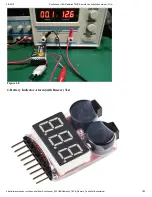
1. Check the back of the Battery Indicator alarm, find the cathode pin marked with “-” (
①
of Figure 2-1).
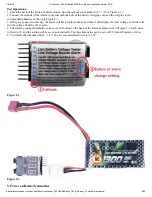
2. Connect the cathode of the Alarm to the first cathode hole of the battery charging cord and the rest pins to the
corresponding headers as shown in Figure 2-2.
3. If they are connected correctly, the alarm will beep for three times, and then it will display the total voltage of all the cells
and the voltage of each cell, in cycle.
4. The warning voltage threshold can be set by the button on the back of the alarm as shown in
②
of Figure 2-1. Each press
will add 0.1V and the setting will be saved automatically. The threshold value can be set to OFF (turn off alarm), or from
2.7V (default after manufactured) – 3.8V. You are recommended to set it to 3.7V.
Figure 2-1
Figure 2-2
3. Power on Radio Transmitter


