background image

8054 and 8054BK


3  

rev.06/11/18

1

2

3
4
5

6

8

9

10

11

12

13

14

15

18

7

16

17

19

16A

ASSEMBLY INSTRUCTIONS

4.

5.

6.

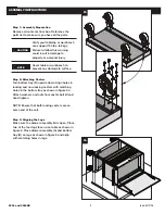
Step 4: Attaching the Handles

Align the other legs with the front corners of the 
bottom tray and drawer assembly and let them 
rest on top as shown in figure 4. Align the hole 
on the handle with the second hole down on the 
drawer assembly and (un-attached) leg as shown 
in figure 4. Insert handle bolts through handle, 
through the leg, and into the drawer assembly as 
shown in figure 4. Secure with washer and nut 
from handle bolt kit and hand tighten. 

Step 5: Attaching Bottom Tray and Drawer 
Assembly to Legs

Once handle is attached, align holes in legs with 
matching holes in bottom tray (B) and drawer 
assembly (A) as shown in figure 5. Insert leg bolts 
through legs and into bottom tray and/or drawer 
assembly and secure from the inside with leg 
washers and nuts until all side holes have been 
attached and hand tightened.

Step 6: Securing Legs

Using two people, turn the cart upright. Continue 
to bolt through aligned holes in the front and 
back of the cart with the leg bolts, washers, and 
nuts as shown in figure 6. Hand tighten. ALL 
holes should now be aligned and secured.

Step 7: Tightening Bolts

Use a 13mm wrench and ratchet with 13mm 
socket or adjustable wrench to tighten all 
bolts. Once all bolts are tightened, your cart is 
complete. See page 4 for parts breakdown.

Summary of Contents for 8054

Page 1: ...tor s native language by the purchaser owner or his designee making sure that the operator comprehends its contents TOOLS NEEDED Read and follow all instructions in User s Manual Do not load carts beyond rated capacity 500 lbs Top Bin and Bottom Shelf 140 lbs each Top Middle and Bottom Drawers 70 lbs each Lock lid and drawers before moving Apply brake on locking casters anytime cart is in place Un...

Page 2: ...to surface Step 2 Attaching Casters Turn bottom tray B upside down Align holes in locking and non locking casters with matching holes in the bottom tray as shown in figure 2 a Attach washers and nuts from caster bolt kit and hand tighten NOTE Ensure that both locking casters are on same end of the cart Step 3 Aligning the Legs Make sure the drawer assembly lid is open Place two of the four legs fa...

Page 3: ...Legs Once handle is attached align holes in legs with matching holes in bottom tray B and drawer assembly A as shown in figure 5 Insert leg bolts through legs and into bottom tray and or drawer assembly and secure from the inside with leg washers and nuts until all side holes have been attached and hand tightened Step 6 Securing Legs Using two people turn the cart upright Continue to bolt through ...

Page 4: ...BK Spray can divider Black 13 RS8050LGR Leg ea Red 4 RS8050LGBK Leg ea Black PARTS BREAKDOWN Item Part Description Req d 14 8054BD 5 Bottom Drawer Red 1 8054BDBK 5 Bottom Drawer Black 15 RS8054DHP Plastic end Piece for Drawer Handle 8 16 RS8054DHL Long Aluminum Drawer Handle each 2 16A RS8054DHS Short Aluminum Drawer handle each 2 17 RSLKS Lock with Keys 1 18 RS80546LK Liner Kit for Top Drawers Bo...

Page 5: ... discutidas con el operador en el idioma materno del operador por parte del comprador propietario o su designado asegurándose que el operador comprenda el contenido HERRAMIENTAS REQUERIDAS Lea y comprenda todas las instrucciones en el manual del usuario Máxima capacidad de carga 500 lbs El estante superior e inferior 140 lbs cada uno El cajón central e inferior 70 lbs cada uno Las unidades pueden ...

Page 6: ...agujeros de las rodajas de cierre y de las sin cierre con los agujeros que coinciden en la charola inferior según se ilustra en la figura 2 a Sujete las arandelas la arandela de presión y las tuercas provistas en el equipo de sujeción de las rodajas y apriételas manualmente NOTA Asegúrese que las dos rodajas de cierre estén del mismo extremo del carro Paso 3 Alineación de las patas Asegúrese que l...

Page 7: ...ros con los agujeros que coinciden en la charola inferior A y en el conjunto de los cajones B según se ilustra en la figura 5 Inserte los pernos de las patas por las patas y en la charola inferior y o en el conjunto de los cajones y asegúrelos desde el interior con las arandelas y tuercas de las patas hasta que todos los agujeros laterales hayan sido sujetados y apretados manualmente Paso 6 Sujeta...

Page 8: ...ité devront être lues et discutées avec l opérateur dans sa langue maternelle par l acheteur propriétaire ou toute personne habilitée par lui à le faire en s assurant que l opérateur en comprend bien le contenu Lea y comprenda todas las instrucciones en el manual del usuario Máxima capacidad de carga 500 lbs Tablettes supérieure et inférieure 140 lbs chacune Tiroirs central et inférieur 70 lbs cha...

Page 9: ...u inférieur B à l envers Alignez les trous des roulettes verrouillables et celles non verrouillables avec les trous du plateau inférieur comme illustré à la figure 2 a Attachez les rondelles la rondelle de frein et les écrous provenant de la trousse de boulons de la roulette et serrez manuellement REMARQUE Assurez vous que les roulettes verrouillables sont placées à la même extrémité du chariot 3e...

Page 10: ...avec les trous du plateau inférieur A et du tiroir B comme illustré à la figure 5 Insérez les boulons de la patte à travers les pattes et dans le plateau inférieur et ou le tiroir et fixez de l intérieur avec les rondelles et les douilles jusqu à ce que tous les trous latéraux ont été attachés et serrez manuellement 6e étape Fixation des pattes À l aide d une autre personne mettez le chariot debou...

Reviews: