

NO
:
101-600-0155-01
Issue:1.0
Table
2
-
1
Front
panel
description
Port Name
Description
HDD
Indicator
The hard disk of the NVR must be provided by the user. Take the
following steps to install hard disks
:
Step 1
Remove the screws for fixing the cover and take down the
cover.
Step 2 Take out the screws and silicone cushion, route the screws
through the silicone cushion, and install it to the screw
holes, as shown in figure 3-1.
Figure
3
-
1
Installing the hard disk screws
Hard disk status indicator
This indicator flashes when data is transmitted.
KB/MOUSE
Supports connection to a USB mouse and
keyboard.
BACKUP
Supports connection to a USB flash drive or
USB removable hard disk.
PWR
Indicator
When the NVR is operating, the PWR indicator
is steady on.When the NVR is shut down, the
PWR indicator is turned off.
Network Video Recorder(NVR)
Quick Setup Guide
Fully understand this document before using this device, and
strictly observe rules in this document when using this device. If
you install this device in public places, provide the tip "You have
entered the area of electronic surveillance" in an eye-catching
place. Failure to correctly use electrical products may cause fire
and severe injuries.
It alerts you to moderate dangers which, if not
avoided, may cause minor or moderate injuries.
It alerts you to risks. Neglect of these risks may
cause device damage, data loss, device
performance deterioration, or unpredictable results.
It provides additional information.
Strictly observe installation requirements when installing the
device. The manufacturer shall not be held responsible for
device damage caused by users' non-conformance to these
requirements.
Strictly conform to local electrical safety standards and use
power adapters that are marked with the LPS standard when
installing and using this device. Otherwise, this device may be
damaged.
Use accessories delivered with this device. The voltage must
meet input voltage requirements for this device.
If this device is installed in places with unsteady voltage, ground
this device to discharge high energy such as electrical surges in
order to prevent the power supply from burning out.
When this device is in use, ensure that no water or any liquid
flows into the device. If water or liquid unexpectedly flows into
the device, immediately power off the device and disconnect all
cables (such as power cables and network cables) from this
device.
Do not focus strong light (such as lighted bulbs or sunlight) on
Precautions
NOTE
CAUTION
WARNING
WARNING
Special Announcement
For more information
,
please refer to CD and website.
Avoid heavy loads, intensive shakes, and soaking to prevent
damages during transportation and storage. The warranty does
not cover any device damage that is caused during secondary
packaging and transportation after the original packaging is
taken apart.
Protect this device from fall-down and intensive strikes, keep the
device away from magnetic field interference, and do not install
the device in places with shaking surfaces or under shocks.
Clean the device with a soft dry cloth. For stubborn dirt, dip the
cloth into slight neutral cleanser, gently wipe the dirt with the
cloth, and then dry the device.
Do not jam the ventilation opening. Follow the installation
instructions provided in this document when installing the device.
Keep the device away from heat sources such as radiators,
electric heaters, or other heat equipment.
Keep the device away from moist, dusty, extremely hot or cold
places, or places with strong electric radiation.
If the device is installed outdoors, take insect- and moisture-
proof measures to avoid circuit board corrosion that can affect
monitoring.
Remove the power plug if the device is idle for a long time.
All complete products sold by the manufacturer are delivered
along with nameplates,
and accessories after
strict inspection. The manufacturer shall not be held responsible
for counterfeit products.
The manufacturer will update this manual according to product
function enhancement or changes and regularly update the
software and hardware described in this manual. Update
information will be added to new versions of this manual without
prior notice.
This manual may contain misprints, technology information that
is not accurate enough, or product function and operation
description that is slightly inconsistent with the actual product,
the final interpretation of company is as a standard.
This manual is only for reference and does not ensure that the
information is totally consistent with the actual product. For
consistency, see the actual product.
quick setup guide
NOTE
this device. Otherwise, the service life of the image sensor may
be shortened.
If this device is installed in places where thunder and lightning
frequently occur, ground the device nearby to discharge high
energy such as thunder strikes in order to prevent device
damage.
CAUTION
Open the package, check the appearance of product for no
obvious damage, and confirm the item
for
1-1 is
consistent.
list
table
Table 1
-
1
Packing list
Open Package Examination
1
2.1 Device Ports
Different device may have different ports and
, please refer to the
.
multi-head
cable
actual product
NOTE
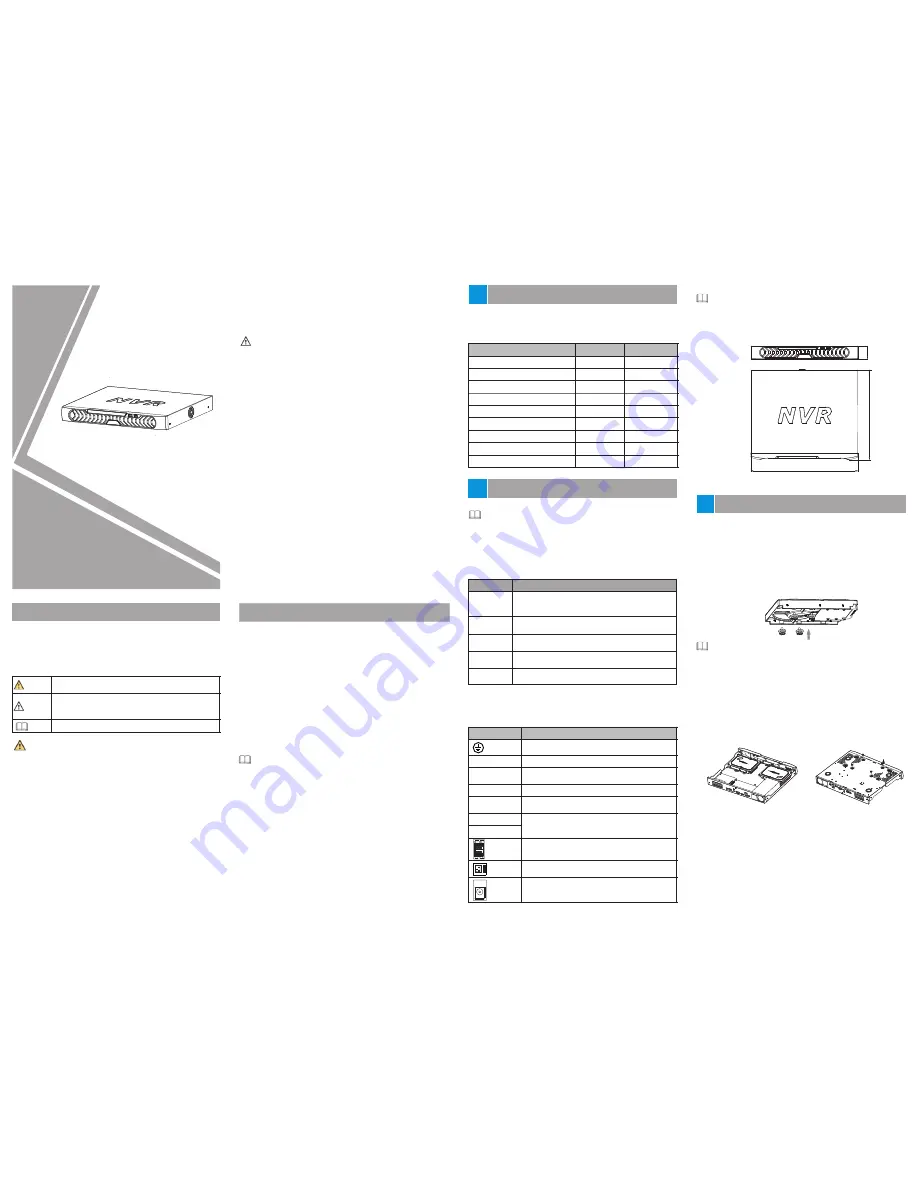
Device Structure
2
2
.
2
Device Dimensions
Different device may have different dimensions, please refer
to the
.
actual product
NOTE
3 Device
Installation
Figure
2-1
Dimensions (Unit:mm)
PoE
Indicator
PoE network status indicator
This indicator flashes when data is transmitted.
RESET
Factory reset button
LAN
RJ45 10 /100/1000 Mbps adaptive Ethernet
interface.
Step 3 Route the screws through the holes on the base, push the
hard disk to the appropriate position on the left, as shown in
figure 3-2.
Turn the device over, and fasten the rest two hard disk
fixing screws, as shown in figure 3-3.
Step 4
Network Video Recorder
Phillips head screw
Silicone cushion
Power cord
Power adapter
Mouse
CD-ROM
Quick Setup Guide
1
Terminal block
1
12
8
1
1
1
1
2
311.8
372
44.5
KB/MOUSE
BACKUP
LINE OUT/
LINE IN
Audio output and audio input
Component
HDMI
VGA
Video output interface
Alarm input and alarm output
110 V/220 V AC power input interface of the
device
Connected to an external power adapter
Port Name
Description
PoE
PoE network interfaces
Safe ground screw of the device
Table
2
-
2
Rear
panel
description
During the installation, ensure that the large disc of the silicon
cushion close to the hard disk screw holes.
Please install the hard disk fixing screws on the screw holes far
away from the power supply interface.
NOTE
Figure3
-
2
Installing
hard
disk
S
tep
5 Install other hard disks following step 2,step 3 and step 4,
and insert the hard disk data cable and power cable, then
put on the upper cover and fasten the fixing screws.
Figure3
-
3
Fixing
hard
disk
Remark
Quantity
Optional
Optional
Front
panel
description of
refer to table 2-1.
device, please
Rear
panel
description of
refer to table 2-2.
device, please
DC 12V


