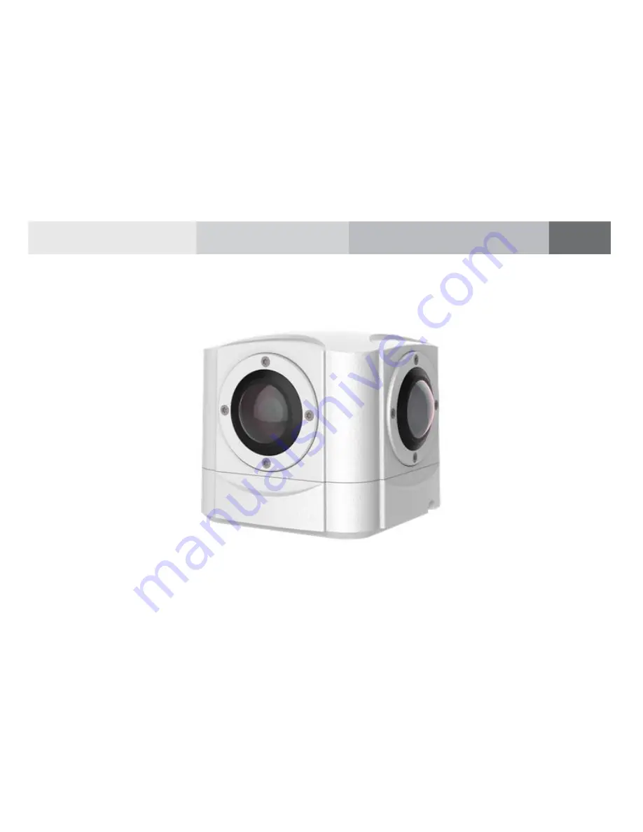
Panoramic Security Surveillance
Network Camera
User Manual
Issue
V1.0
Date
2019-01-28
Page 1: ...Panoramic Security Surveillance Network Camera User Manual Issue V1 0 Date 2019 01 28 ...
Page 2: ......
Page 3: ...ollowing symbols whose meanings are described accordingly Symbol Description It alerts you to fatal dangers which if not avoided may cause deaths or severe injuries It alerts you to moderate dangers which if not avoided may cause minor or moderate injuries It alerts you to risks Neglect of these risks may cause device damage data loss device performance deterioration or unpredictable results It pr...
Page 4: ...e detector in Panoramic security surveillance network camera may be permanently damaged If this device is installed in places where thunder and lightning frequently occur ground the device nearby to discharge high energy such as thunder strikes in order to prevent device damage During the outdoor installation prevent the morning or evening sunlight incidence to the lens of the camera The sun shade...
Page 5: ...ed If the fragile sticker is damaged contact customer services or sales personnel The manufacturer shall not be held responsible for any artificial damage of the fragile sticker Special Announcement All complete products sold by the manufacturer are delivered along with nameplates operation instructions and accessories after strict inspection The manufacturer shall not be held responsible for coun...
Page 6: ... Quick Configuration 15 3 1 Login and Logout 15 3 2 Main Page layout 16 3 3 Change the Password 18 3 4 Browse Video 19 3 4 1 Install Plugins 21 3 5 Setting Local Network Parameters 21 4 Parameter Setting 24 4 1 Sensor Setting Interface 24 4 2 Time Segment 25 4 3 Image Setting 25 4 4 Scene 27 4 5 Exposure 27 4 6 White Balance 29 4 7 DayNight 30 4 8 Noise Reduction 31 4 9 Enhance Image 32 5 Configur...
Page 7: ... Manual Contents Issue V1 0 2019 01 28 v 5 5 Alarm 41 5 6 Device Record 42 5 7 Privacy Masking 43 5 8 Network Service 44 5 9 Privilege Manager 44 5 10 Protocol 45 5 11 Device Log 46 5 12 Maintenance 46 5 13 Local Config 47 6 Technical Specifications 48 ...
Page 8: ...360 panoramic views without blind spots making it ideal for wide and open areas such as airport shopping malls banks hotels stores square and more The camera is 8MP single pixel and 32MP four eyes 1 2 Device Structure Figure 1 1 shows the rear panel of the Panoramic Security Surveillance Network Camera For details about the interfaces see Table 1 1 Figure 1 1 Appearance and interfaces of device 90...
Page 9: ...112 2 1 12 2 101 8 10 1 8 31 39 4 31 39 4 31 39 4 31 39 4 4 M8 6mm Table 1 1 Interfaces 1 3 Cable Connection Figure 1 2 the multi connector combination cable of the network camera For details about the multi connector combination cable see Table 1 2 Figure 1 2 Multi connector combination cable ...
Page 10: ...ut port Receives analog audio signals from devices such as a sound pickup device 4 Audio output port Connects to an external audio device such as a speaker 5 Gray core Alarm output terminal A normal open Alarm output Purple core Alarm output terminal B normal open yellow core Alarm input positive terminal Alarm input terminal Orange core Alarm input ground terminal 1 4 Configuration Requirements C...
Page 11: ... the camera Hexagon socket stainless steel screw delivered with the camera 2 2 Installation Mode If the camera is installed indoor a bracket should be selected if the camera is installed outdoor the shield and upright column should be selected NOTE The bracket where the support is mounted must be able to withstand at least three times of the total weight of the support and the camera 2 3 Installat...
Page 12: ...curity surveillance Network Camera User Manual 10 Issue V1 0 2019 01 28 Figure 2 1 Fix the installation block Figure 2 2 Dimension of bracket 91 91 41 φ 47 Step 2 Fix the mounting bracket on the pole as shown in Figure 2 3 ...
Page 13: ...0 2019 01 28 11 Figure 2 3 Fix the mounting bracket Step 3 Install with Column Align the camera adapter with the adapter hole on the column and when it is in place fix the two with screws and confirm that fixing screw is fixed in the groove of the adapter as shown in Figure 2 4 ...
Page 14: ...s Panoramic security surveillance Network Camera User Manual 12 Issue V1 0 2019 01 28 Figure 2 4 Install with column Groove Step 4 Install on ceiling Fix the mounting bracket on the pole as shown in Figure 2 5 ...
Page 15: ... 0 2019 01 28 13 Figure 2 5 Fix the mounting bracket Step 5 Install on ceiling Align the camera adapter with the adapter hole on the column and when it is in place fix the two with screws and confirm that fixing screw is fixed in the groove of the adapter as shown in Figure 2 4 ...
Page 16: ...Contents Panoramic security surveillance Network Camera User Manual 14 Issue V1 0 2019 01 28 Figure 2 6 Install in ceiling Groove End ...
Page 17: ... 168 0 120 in the address box and press Enter The login page is displayed as shown in Figure 3 1 Figure 3 1 Login page Step 2 Input the User and password The default name and password are both admin Modify the password when you login the system for first time to ensure system security After modifying password you need to wait at least three minutes then power off to make sure modifying successfull...
Page 18: ...an view real time video set parameter Video parameter Video control and logout of the system Figure 3 2 is shown the main page layout Table 3 1 lists the elements on the main page layout Figure 3 2 Main page layout 1 2 3 4 5 6 7 8 9 10 11 12 13 14 15 Table 3 1 Elements on the main page No Element Description 1 Real time video area Real time videos are played in this area User can also set sensor p...
Page 19: ...on it will access to sensor setting 12 Snapshot Click the icon it will snapshot 13 Local record Click the icon it will record video and save to local folder 14 Mode Panoramic mode fisheye mode crystal ball mode prospective mode planet mode as shown in figure 3 3 to figure 3 6 15 Intelligent analysis Open or close intelligent analysis When the live video is full screen user can use keyboard shortcu...
Page 20: ...Camera User Manual 18 Issue V1 0 2019 01 28 Figure 3 3 Prospective mode Figure 3 4 Crystal ball mode Figure 3 5 Fisheye mode Figure 3 6 Planet mode End 3 3 Change the Password Description User can click to change the password for logging to the system ...
Page 21: ...an 3 times please login again after 5 minutes Step 2 Input the old password new password and confirmation password Step 3 Click OK If the message Change own password success is displayed the password is successfully changed If the password fails to be changed the cause is displayed For example the new password length couldn t be less than eight Step 4 Click OK The login page is displayed End 3 4 B...
Page 22: ...gure 3 8 Add the a trusted site Step 2 In the Internet Explorer choose Tool Internet Options Security Customer level and set Download unsigned ActiveX control and initialize and script ActiveX controls not marked as safe for scripting under ActiveX controls and plug ins to Enable as shown in Figure 3 9 Figure 3 9 Configuring ActiveX control and plug ins ...
Page 23: ...rst time Figure 3 10 Install plugin Procedure Step 1 Click the message download and install the plugin follow the prompts Step 2 During installing user should close the browser Step 3 Reopen the browser after installation End 3 5 Setting Local Network Parameters Description Local network parameters include IP protocol IP address Subnet mask Default gateway Dynamic Host Configuration Protocol DHCP ...
Page 24: ...uses an address length of 128 bits Setting method Select a value from the drop down list box Default value IPv4 DHCP The device automatically obtains the IP address from the DHCP server Setting method Click the option button NOTE To query the current IP address of the device you must query it on the platform based on the device name DHCP IP IP address that the DHCP server assigned to the device DH...
Page 25: ...thod Enter a value manually Default value 192 168 0 2 MTU Set the maximum value of network transmission data packets Setting method Enter a value manually NOTE The MTU value is range from 800 to 1500 the default value is 1500 Please do not change it arbitrarily Step 3 Click OK If the message Apply success is displayed click OK The system saves the settings The message Set network pram s success Pl...
Page 26: ...e 4 1 Figure 4 1 Sensor Setting Table 4 1 Right click setting parameters Parameter Description Setting Full screen Click it the live video will display in full screen Setting method Click Sensor Set parameters of sensor more details please refer next chapters Setting method Click Zoom In Zoom Out N A Setting method Click Restore Panorama When the live video is zoom in or out click the icon to rest...
Page 27: ...rface Figure 4 2 Time segment interface Operation Procedure Step 1 Click in the lower left corner of Sensor Setting and choose Debug Mode Step 2 Tick Enable Step 3 Set the Start Time Step 4 Set the End Time Step 5 Click Save the message Save success is displayed the system saves the settings End 4 3 Image Setting Figure 4 3 shows the image setting interface ...
Page 28: ...etting method Drag the slider Default value 50 Sharpness It indicates the sharpness of the image plane and the sharpness of the image edge The shaper the image the better detail contrast Setting method Drag the slider Default value 50 Saturation It indicates the color will be more gorgeous if the value is higher Setting method Drag the slider Default value 50 Contrast It indicates the contrast bet...
Page 29: ... Camera User Manual Parameter Setting Issue V1 0 2019 01 28 27 4 4 Scene Figure 4 4 shows the scene interface Figure 4 4 Scene interface Scene Indoor and Outdoor Mirror Normal and Rotation 4 5 Exposure Figure 4 5 shows the exposure interface ...
Page 30: ...Setting Shutter Priority You can set Shutter Setting to fixed values The iris and gain are automatically adjusted by the system Setting method Select a value from the drop down list Default value Auto Meter area It is used to select the metering area Whole During metering all areas of an image have an equal weight that is all areas are involved in the metering Center pot During metering the centra...
Page 31: ... is less than or equal to the value of this parameter Setting method Select a value from the drop down list Default value 1 25 Max Gain The device automatically adjusts the gain based on the external light The gain is less than or equal to the value of this parameter Setting method Drag the slider Default value 50 4 6 White Balance Figure 4 6 shows the white balance interface Figure 4 6 White bala...
Page 32: ...nual In manual WB mode you can manually select a WB mode based on the monitoring environment Setting method Select a value from the drop down list Default value Auto Red Gain It indicates the gain applied to red channels As the value increases the color temperature becomes lower This parameter is valid when Manual Mode is set to Customized Setting method Drag the slider Default value 0 Blue Gain I...
Page 33: ...Table 4 5 DayNight parameters description Parameter Meaning Configuration Method D N Setting Mode It can be only set to Day Mode Day mode The image is colored and the filter is in the day state preventing infrared light from entering the sensor Default value Day Mode 4 8 Noise Reduction Figure 4 8 shows the Noise reduction interface ...
Page 34: ...ters on the Noise reduction interface Parameter Description Setting 2 DNR Decrease the image noise How to set Select from the drop down list box Drag the slider to adjust max strength Default value Auto 3 DNR Decrease the image noise How to set Select from the drop down list box Drag the slider to adjust max strength Default value Auto End 4 9 Enhance Image Figure 4 9 shows the Enhance Image inter...
Page 35: ...ter image effect Setting method Tick the WDR mode and drag the slider Default value 50 HLC It provides a clearer view of an image in the highlight environment When HLC is enabled the total brightness of an image is reduced allowing you to view objects in front of the highlight Setting method Tick the HLC mode and drag the slider Default value 50 BLC It provides a clearer view of an image in the ba...
Page 36: ...amera User Manual 34 Issue V1 0 2019 01 28 DeFog It provides a clearer view of an image in the fogged environment when Defog is enabled As the value increases the image becomes clearer Setting method Tick the Defog mode and drag the slider Default value 50 End ...
Page 37: ...Information User can set device name and view the information of camera on Device info interface Figure 5 1 Device information interface Table 5 1 Device information Parameter Description Setting Device ID Unique device identifier used by the platform to distinguish the devices Setting method The parameter cannot be modified ...
Page 38: ...odification fails Setting method Enter a value manually MAC Address N A Setting method These parameters cannot be modified Camera Type Product Model Manufacturer Name Hardware Version Firmware Version Video Channel s Channel Quantity Alarm Input Quantity Alarm Output Quantity Serial Port Quantity Network card Quantity 5 2 Stream At stream interface users can set Base Stream SVC stream and ROI as s...
Page 39: ...device supports two streams Streams 1 and 2 use the H 264 codec The maximum resolution can be set for streams 1 Only a low resolution can be set for stream 2 Setting method Select a value from the drop down list box Name Stream name NOTE The stream name is combined with Chinese character number character and underline Setting method Enter a value manually The value cannot exceed 32 bytes Default v...
Page 40: ...an that of H 264 Main Profile and the performance of H 264 Main Profile is higher than that of H 264 Base Profile If a hardware decoding device is used select the appropriate codec based on the decoding performance of the device H 264 High Profile has the highest requirements on the hardware performance and H 264 Base Profile has the lowest requirements on the hardware performance H 265 H 265 is t...
Page 41: ...ifferent frequencies are as follows 50 Hz 1 25 f s 60 Hz 1 30 f s NOTE The frequency is set on the Device Configuration Camera page The biggest MJPEG coding format frame rate is 12 frames per second Setting method Select a value from the drop down list I Frame Interval F rame I frames do not require other frames to decode A smaller I frame interval means better video quality but higher bandwidth S...
Page 42: ...nable Only main stream supports smart encode Setting method Click the button on to enable Smart Encode The SVC stream and ROI can be set when the Smart Encode is disabled 5 3 Device User can set Local Network Device Port Date and Time Camera OSD Microphone System and Voice Denoise as shown in Figure 5 3 Figure 5 3 Device interface Device Port Control port http port and RTSP port Date and Time Time...
Page 43: ...e enable or disable the function 5 4 Intelligent Analysis User can set Perimeter Single Virtual Fence Double Virtual Fences Loiter Multi Loiter Object Left Object Removed Abnormal Speed Converse Illegal Parking Signal Bad and Advanced as shown in Figure 5 4 Figure 5 4 Intelligent analysis interface If user wants to enable intelligent analysis he needs to enable the function and set schedule respec...
Page 44: ...ance Network Camera User Manual 42 Issue V1 0 2019 01 28 Figure 5 5 Alarm interface User set parameters of alarm when you need 5 6 Device Record User can set Record Policy and Record Directory on device record interface as shown in Figure 5 6 ...
Page 45: ...ation Issue V1 0 2019 01 28 43 Figure 5 6 Device record interface 5 7 Privacy Masking User can set at most four privacy masking areas as shown in Figure 5 7 Dragging the mouse cursor to choose area to mask click Add to save the area Figure 5 7 Privacy masking interface ...
Page 46: ...Mapping SMTP FTP IP Filter CGI Alarm Service Center and SNMP at network interface as shown in Figure 5 8 Figure 5 8 Network service interface User set the network parameter according to network knowledge Click Apply to save the settings 5 9 Privilege Manager User can add the new user accounts modify or operate the authority of user as shown in Figure 5 9 ...
Page 47: ... Camera User Manual Configuration Issue V1 0 2019 01 28 45 Figure 5 9 Privilege manager interface 5 10 Protocol User can set Protocol Info Security CMS Configuration and Multicast Param as shown in Figure 5 10 Figure 5 10 Protocol interface ...
Page 48: ...e V1 0 2019 01 28 5 11 Device Log User can view the Operation Log and Alarm Log Collect All Log as shown in Figure 5 11 Figure 5 11 Device log interface 5 12 Maintenance User can Restart Update and Restore to Factory Default as shown in Figure 5 12 Figure 5 12 Maintenance interface ...
Page 49: ...iguration Issue V1 0 2019 01 28 47 5 13 Local Config User can set local configuration such as Snapshot picture format Snapshot Save Path Local Record Save Path Local Record File Size and Hardware Decode as shown in Figure 5 13 Figure 5 13 Local config interface End ...
Page 50: ...e Optional PAL or NTSC the default value is PAL Effective pixel 7680 4320 Field angle V 360 H 360 Digital zoom Support The lowest illumination Color 0 002 Lux F 2 2 AGC ON DayNight Color Optical filter Support fixed IR distance N A Shutter speed 1 5 s 1 20K s Gain control Manual Auto the default value is auto White balance Manual Auto the default value is auto Correction of lens aberration Support...
Page 51: ... audio input one audio output Microphone Double Mic Stereo Support Two way voice Support CVBS interface N A SD card interface Reserved Reset Restore factory settings Video features Video encode format H 264 H 265 MJPEG Multiple code streams 4 streams the forth is sub stream support preview and record Image setting Brightness contrast saturation sharpness Bit rate format CBR VBR Synchronous mode In...
Page 52: ...port Preview video mode Tile 360 perspective mode crystal ball mode planet mode auto rotation mode Defog Support ROI Support Time segment Support IO alarm detection Support Privacy mask Support Character display Time date name and user defined characters Security Password protection multi level user group management user define permissions and one key reset Reliability Provide software and hardwar...
Page 53: ...rtuguese Polish Italian Russian French Hungarian Czech Support browsers Windows IE 8 or later version Firefox Chrome Manager and maintenance Not Supported Web upgrade separate upgrade tools Web interface style Customization standard Other Power supply DC 12 V POE Operating temperature 40 C to 60 C Operating humidity RH 90 MAX no condensation EMC level Conform to CE FCC and ministry of public secur...