The Disk board kit contains:
■
One Disk board
■
One 80-cm SCSI cable
■
One Fast/Wide SCSI terminator
To install the Disk board you will need:
■
Phillips #1 screwdriver
■
Grounding wrist strap
A padded ESD mat is also required if you perform any work on the board.
The padding prevents breakage of parts on the bottom of the board.
Disk Board SCSI ID Numbers
The Disk board is ready for installation, and it is not necessary for you to
manually set SCSI drive ID numbers. The default SCSI ID numbers for
Disk drives, which are located on the Disk boards, are based on the board
slot number.
Each Disk has an ID_ENABLE jumper and four ID jumpers.
■
If the ID_ENABLE jumper is not installed, the disk drive uses the
default SCSI ID.
■
If the ID_ENABLE jumper is installed, the disk drive uses the ID
specified by the four ID jumpers located on the Disk board.
For details, refer to Appendix C, “SCSI Devices” in the Enterprise server
system reference manual that came with your system.
Hot-Plug Features
Sun™ Enterprise™ servers have an Automatic System Reconfiguration
(ASR) feature that reboots the system in a configuration that omits failed
components (such as CPUs, memory, or I/O bus). In this configuration the
board containing the failed components is placed in low-power mode and
is no longer accessible.
Caution –
If the message:
NOTICE: Hot Plug not
supported in this system
is displayed during boot, do
NOT attempt to remove or install a board in a powered-on
system or hardware damage will occur.
The hot-plug feature enables you to insert a new board into a powered-on
system while the system is supplied with electrical power.
Caution –
Do not attempt hot-plug if the peripheral power
supply is missing or inoperative.The peripheral power supply
provides the precharge voltages required for hot-plug. Use
prtdiag(1M)
to determine the peripheral power supply status.
When a working board is added to a powered-on system with the hot-plug
feature, the system cannot use the new board until the system is rebooted.
Removing a Board
Note –
All empty board slots must have filler panels (Enterprise 5x00/
4x00) or load boards (Enterprise 6x00) to ensure proper cooling. For
information on filler panels and load boards, refer to Chapter 5 in the
Enterprise server systems reference manual that came with your server.
1. Ensure that the board is in low-power mode and ready for removal.
If the board is not in low-power mode, halt the system and turn off the
power before proceeding. The board is in low-power mode if one of
the following is true:
■
The three LEDs on the board are not lit (board has no power).
■
The outer two green LEDs are not lit and the middle yellow LED is lit
(board in low-power mode).
Caution –
Use a grounding wrist strap to prevent static damage.
2. With a Phillips #1 screwdriver, turn the two quarter-turn access slots
to the unlocked position (
).
3. Unfasten any cable connectors from the front panel and set them
aside.
Label the cables to identify them for reconnection later.
4. Pull the ends of both extraction levers toward you, then gently pull
the board out of the card cage.
Do not let the components on the board catch on any surrounding
surfaces as you pull the board.
5. Place the board on a padded ESD mat for servicing, or store the board
in an antistatic bag.
Installing a Disk Board
■
In Enterprise 5x00/4x00 systems, four Disk boards can be installed.
■
In Enterprise 6x00 systems a maximum of two Disk boards can be
installed.
Note –
Disk boards can be installed only in slots 14 and 15 in Enterprise
6x00 systems, and slot 15 must be used when installing only one Disk board.
1. Select a board slot.
Refer to your server systems reference manual for rules for selecting a
board slot.
2. Open the extraction levers by pulling the ends of both levers toward
you.
Caution –
Use a grounding wrist strap to prevent static damage.
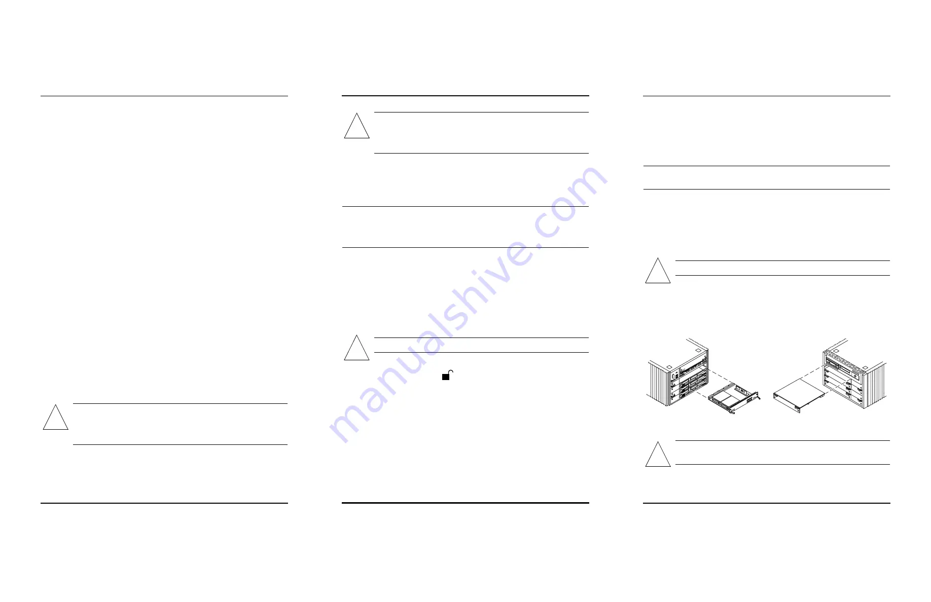
3. Insert the board into the card cage slot.
■
For a front slot, orient the board component-side down.
■
For a rear slot, orient the board component-side up.
4. Use the extraction levers to seat the board on the centerplane.
Caution –
Do not press on the board front panel to seat it—
doing so will damage the connector pins.
!
!
!
!
Rear view
Front view
!


