


64
| Optidrive P2 User Guide |
Version 3.07
www.invertekdrives.com
9. Serial Communications
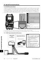
9.1. RS-485 Communications
Optidrive P2 has an RJ45 connector located within the wiring enclosure of the drive. This connector allows the user to set up a drive
network via a wired connection. The connector contains two independent RS485 connections, one for Invertek’s Optibus Protocol
and one for Modbus RTU / CANBus. Both connections can be used simultaneously. The Optibus connection is always available,
and can be used simultaneously with other interfaces, however only one other interface may be used, e.g. If Modbus RTU is in use,
CAN is disabled. If a Fieldbus Option Module (E.g. Profibus) is inserted into the drive, both Modbus and CAN are disabled. The
electrical signal arrangement of the RJ45 connector is shown as follows:
1
CAN-
2
CAN+
3
0 Volts
4
Optibus / Remote Keypad / PC Connection
5
Optibus / Remote Keypad / PC Conn
6
+24 Volt
7
-RS485 (Modbus RTU)
8
+RS485 (Modbus RTU)
Warning:
This is not an Ethernet connection. Do not connect
directly to an Ethernet port.
Warning:
When using Modbus RTU or CANopen, ensure that
the 0V signal (T3) is also used to avoid comms errors
and potentially damaging common mode voltages.
The Optibus data link is only used for connection of Invertek peripherals and inter-drive communication.
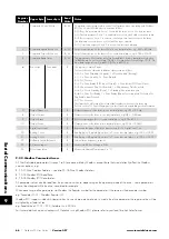
The Modbus interface allows connection to a Modbus RTU network as described in section
9.2. Modbus RTU Communications.
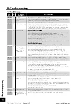
9.1.1. RS-485 Communications Electrical Connections
Modbus RTU
RS485 Controller
RS485+
RS485-
0 Volt / Common
Ground
NOTES
• Use 3 or 4 Conductor Twisted Pair Cable
• RS485+ and RS485- must be twisted pair
• Ensure the network taps for the drive
are kept as short as possible
• Using Option OPT-2-BNTSP-IN is
preferred
• Terminate the network cable shield at
the controller only. Do not terminate at
the drive!
• 0 Volt common must be connected
across all devices and to reference 0 Volt
terminal at the controller
• Do not connect the 0V Common of the
network to power ground
RS485+
RS485-
0 Volt / Common
Shield
OPT-2-BNTSP-IN
OPT-2-BNTSP-IN
1 2
3
RS485+
0
Volt / Commo
n
Connection to the
drive through the
option
OPT-2-BNTSP-IN
RS485-
Pin 3 – 0 Volt / Common
Pin 7 – RS485- (Modbus RTU)
Pin 8 – RS485+ (Modbus RTU)
RJ45 connector pinout
Direct connection to the drive
through the built-in RJ45 port
1 2 3 4 5 6 7 8
12345678
9
Serial Communications


